Stereoscopic image conversion panel and stereoscopic image display apparatus having the same

a stereoscopic image and display panel technology, applied in the field of stereoscopic image conversion panel and can solve the problems of reducing image display quality, difficulty in forming an alignment groove on an alignment film formed on the concave lens, and reducing brightness and alignment properties, so as to achieve the effect of enhancing the display quality of the stereoscopic image display apparatus

Active Publication Date: 2007-08-23
SAMSUNG DISPLAY CO LTD
View PDF2 Cites 48 Cited by
  • Summary
  • Abstract
  • Description
  • Claims
  • Application Information

AI Technical Summary

Benefits of technology

[0012]The present invention provides a stereoscopic image conversion panel enhancing image display quality to increase brightness and alignment properties.
[0019]Therefore, since the stereoscopic image lens part is rearranged by an electric field generated between the upper and lower transparent electrodes and a refractive index is changed according to the position, a stereoscopic image can be produced by refracting light polarized to have a predetermined direction, and thus a display quality of the stereoscopic image display apparatus may be enhanced.

Problems solved by technology

In the lenticular type, since a concave lens is used, forming an alignment groove on an alignment film formed on the concave lens is difficult.
Therefore, when the parallax-barrier type or the lenticular type of stereoscopic image display apparatus is employed without using the extra glasses, the brightness and alignment properties are reduced, thus reducing the image display quality.

Method used


Image

  • Stereoscopic image conversion panel and stereoscopic image display apparatus having the same
  • Stereoscopic image conversion panel and stereoscopic image display apparatus having the same
  • Stereoscopic image conversion panel and stereoscopic image display apparatus having the same

Examples


example embodiment 1

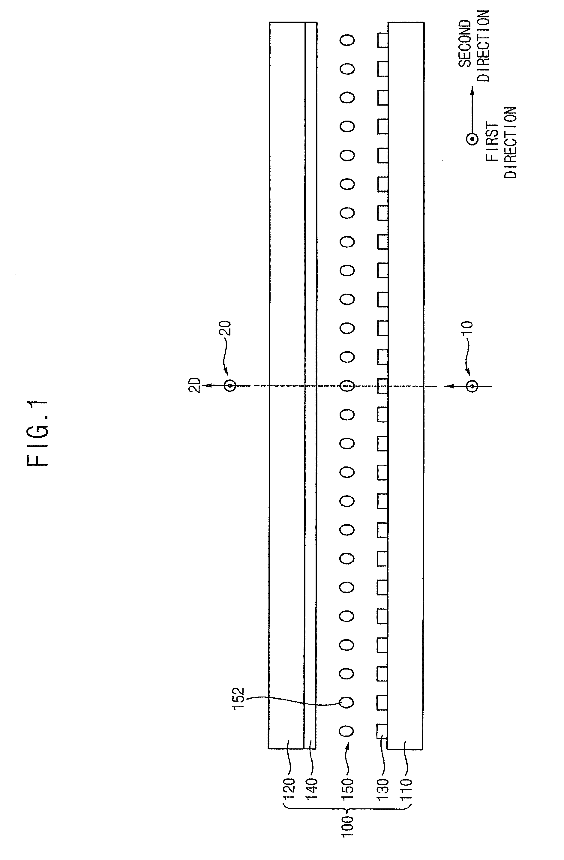
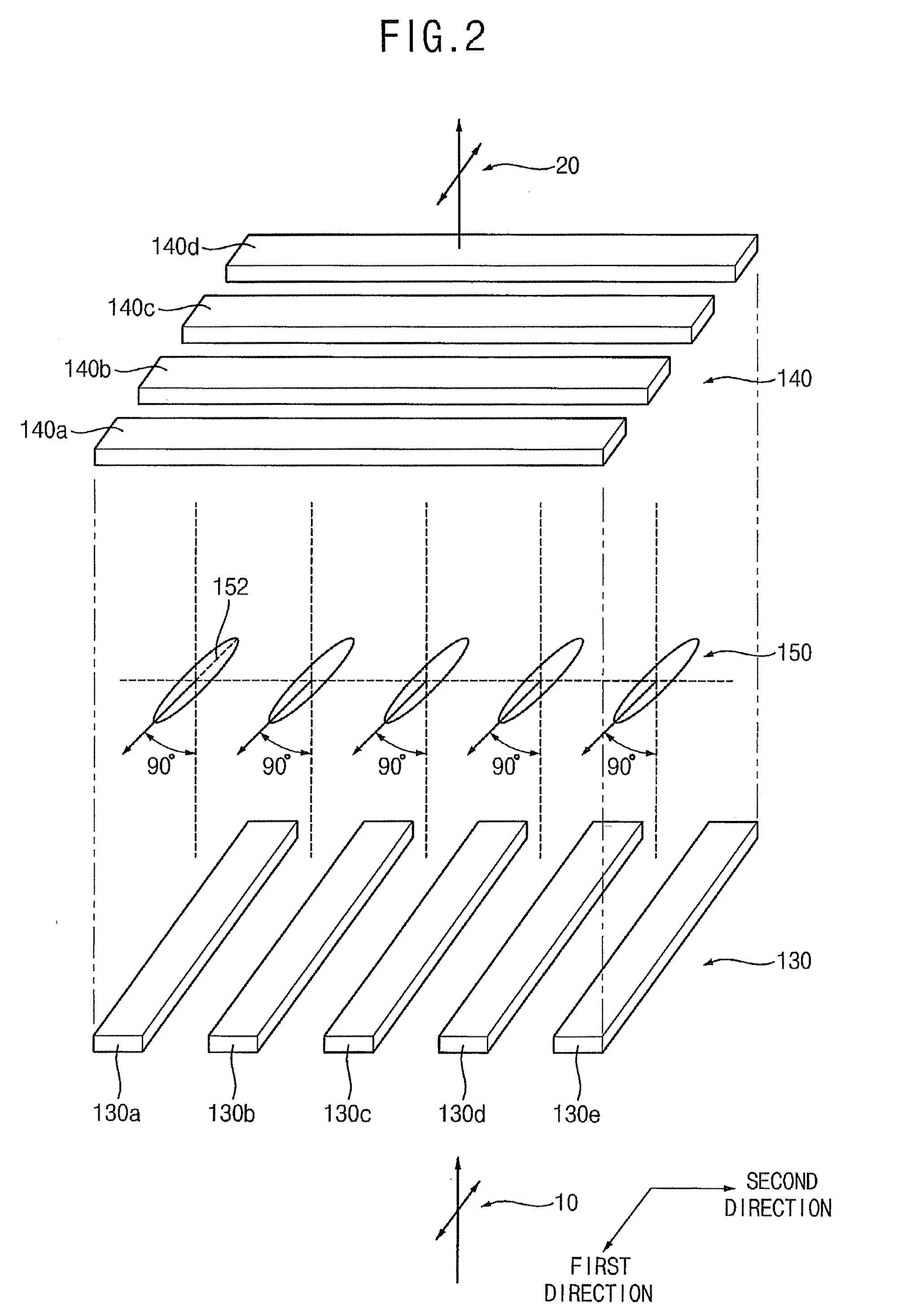
[0042]FIG. 1 is a cross-sectional view illustrating a stereoscopic image conversion panel according to a first exemplary embodiment of the present invention, and FIG. 2 is an enlarged perspective partial view illustrating the stereoscopic image conversion panel in FIG. 1.

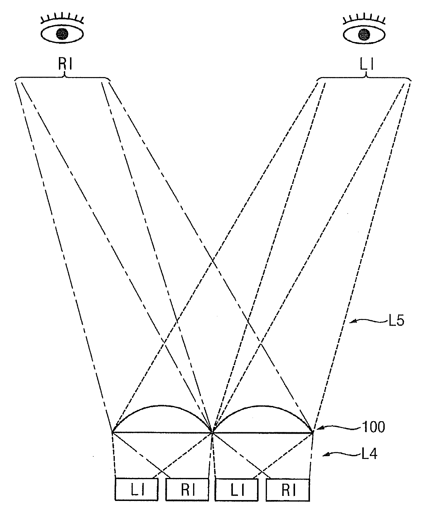
[0043]Referring to FIGS. 1 and 2, the stereoscopic image conversion panel 100 according to the first exemplary embodiment includes a lower transparent substrate 110, an upper transparent substrate 120, lower transparent electrodes 130, upper transparent electrodes 140 and a liquid crystal lens layer 150. The stereoscopic image conversion panel 100 displays a flat image applied from a lower part, or converts the flat image into a stereoscopic image to display the stereoscopic image.

[0044]The lower transparent substrate 110 has a plate-like shape and includes, for example, transparent glass, quartz or synthetic resins. The upper transparent substrate 120 also has a plate-like shape and includes, for example, transpare...

example embodiment 2

[0081]FIG. 8 is a cross-sectional view illustrating a stereoscopic image conversion panel according to a second exemplary embodiment of the present invention, and FIG. 9 is an enlarged perspective partial view illustrating the stereoscopic image conversion panel in FIG. 8.

[0082]Referring to FIGS. 8 and 9, the stereoscopic image conversion panel 100 according to the exemplary embodiment includes a lower transparent substrate 110, an upper transparent substrate 120, lower transparent electrodes 130, upper transparent electrodes 140, a liquid crystal lens layer 150, an upper alignment film (not shown) and a lower alignment film (not shown).

[0083]The lower and upper transparent substrates 110 and 120 have a plate-like shape, are formed of a transparent material and are disposed facing each other.

[0084]The lower transparent electrodes 130 are formed on the lower transparent substrate 110 facing the upper transparent substrate 120. The lower transparent electrodes 130 are formed lengthwis...

example embodiment 3

[0102]FIG. 12 is a cross-sectional view illustrating a stereoscopic image display apparatus according to a third exemplary embodiment of the present invention. The stereoscopic image conversion panel in the stereoscopic image display apparatus of this exemplary embodiment is substantially the same as Example Embodiment 1 or Example Embodiment 2 of the stereoscopic image conversion panels. Thus, the same reference numerals will be used to refer to the same or like parts as those described in Example Embodiment 1 or Example Embodiment 2 of the stereoscopic image conversion panels and any further repetitive explanation concerning the above elements will be omitted.

[0103]Referring to FIG. 12, the stereoscopic image display apparatus according to this exemplary embodiment includes a backlight assembly 200, a display panel assembly 300 and a stereoscopic image conversion panel 100.

[0104]The backlight assembly 200 includes a light source (not shown) emitting a first light L1. The display p...


PUM


Abstract

In a stereoscopic image conversion panel for enhancing display quality and a stereoscopic image display apparatus having the panel, the stereoscopic display panel includes lower and upper transparent substrates, lower and upper transparent electrodes, and a liquid crystal lens layer. The lower and upper transparent substrates face each other. The lower transparent electrodes are disposed on the lower transparent substrate, formed along a first direction, and formed substantially in parallel with each other along a second direction. The upper transparent electrodes are disposed on the upper transparent substrate, formed along the second direction, and formed substantially in parallel with each other along the first direction. The liquid crystal lens layer is disposed between the upper and lower transparent substrates, and a longitudinal arrangement direction of liquid crystal molecules of the liquid crystal lens layer is changed by an electric field to have a predetermined refractive index. Therefore, a refracted incident light produces a stereoscopic image for enhancing display quality.

Description

[0001]The present application claims priority to Korean Patent Application No. 2006-16059, filed on Feb. 20, 2006, and all the benefits accruing therefrom under 35 U.S.C. § 119, the contents of which in its entirety are herein incorporated by reference.BACKGROUND OF THE INVENTION[0002]1. Field of the Invention[0003]The present invention relates to a stereoscopic image conversion panel and a stereoscopic image display apparatus having the stereoscopic image conversion panel. More particularly, the present invention relates to a stereoscopic image conversion panel for enhancing image display quality and a stereoscopic image display apparatus having the stereoscopic image conversion panel.[0004]2. Description of the Related Art[0005]Nowadays, stereoscopic image display apparatuses to display a three-dimensional (“3-D”) stereoscopic image are being developed according to an increase in demand for 3-D stereoscopic images in the fields of games, movies and so on.[0006]Generally, the stere...

Claims


Application Information

Patent Timeline
Patent Type & Authority Applications(United States)
IPC IPC(8): G02B27/22G02B30/28
CPCG02B27/2214G02F1/29G02F1/134309G02B27/26G02B30/25G02B30/28G02B30/27
Inventor YUN, HAE-YOUNGPARK, WON-SANGLEEAHN, SEON-HONGKIM, SANG-WOOSHIM, CHANG-WOOYEO, YONG-SUKLEE, JAE-YOUNGLIM, JAE-IK
Owner SAMSUNG DISPLAY CO LTD
Why Eureka
Try Eureka