High strength fastener system

a fastener system and high-heavy technology, applied in the direction of fastening means, mechanical equipment, etc., can solve the problems of inefficient manufacturing design of bolt tracks, difficult to retain bolt fasteners together with the second workpiece, and common quarter-turn fasteners that either fatigue prematurely, etc., to achieve the effect of high strength

Inactive Publication Date: 2007-08-23
SCHORLING DETLEF T +1
View PDF18 Cites 55 Cited by
  • Summary
  • Abstract
  • Description
  • Claims
  • Application Information

AI Technical Summary

Benefits of technology

[0009]The high strength fastening system of the present disclosure consists of a bolt fastener assembly and a receptacle assembly which is designed to press together plate members here called work pieces. The work pieces comprise mainly of a lower and an upper plate with circular apertures in each plate. The first work piece which is the lower plate member is engaged to the second work piece which is the upper plate member thru a biased engagement. The first work piece consists of a receptacle that is a cylindrical housing that forms 2 chambers. The second work piece consists of a bolt with a head and is able to slide with respect to the receptacle between an extended and retracted position. Two or more disc springs also called “Bellev

Problems solved by technology

Some of the designs show bolt tracks of inefficient manufacturing design.
In addition it has been difficult to retain a bolt fastener together with the second work piece, as some of the designs show them as non-captive and the bolt fastener might be misplaced or lost when disengage

Method used


Image

  • High strength fastener system
  • High strength fastener system
  • High strength fastener system

Examples


Embodiment Construction

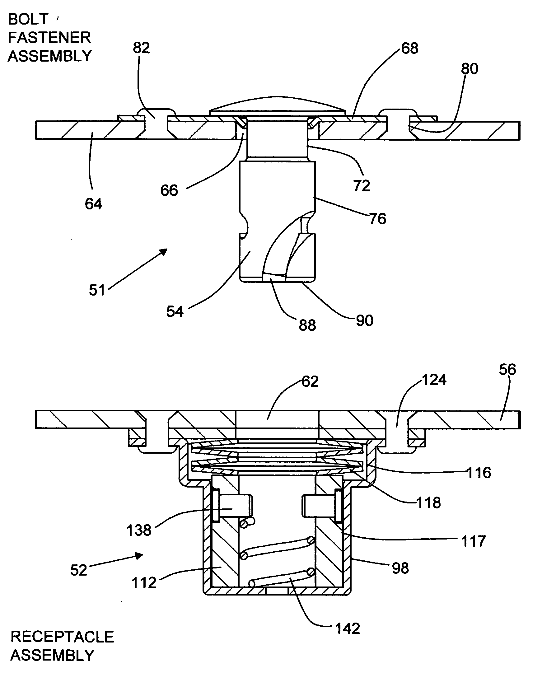
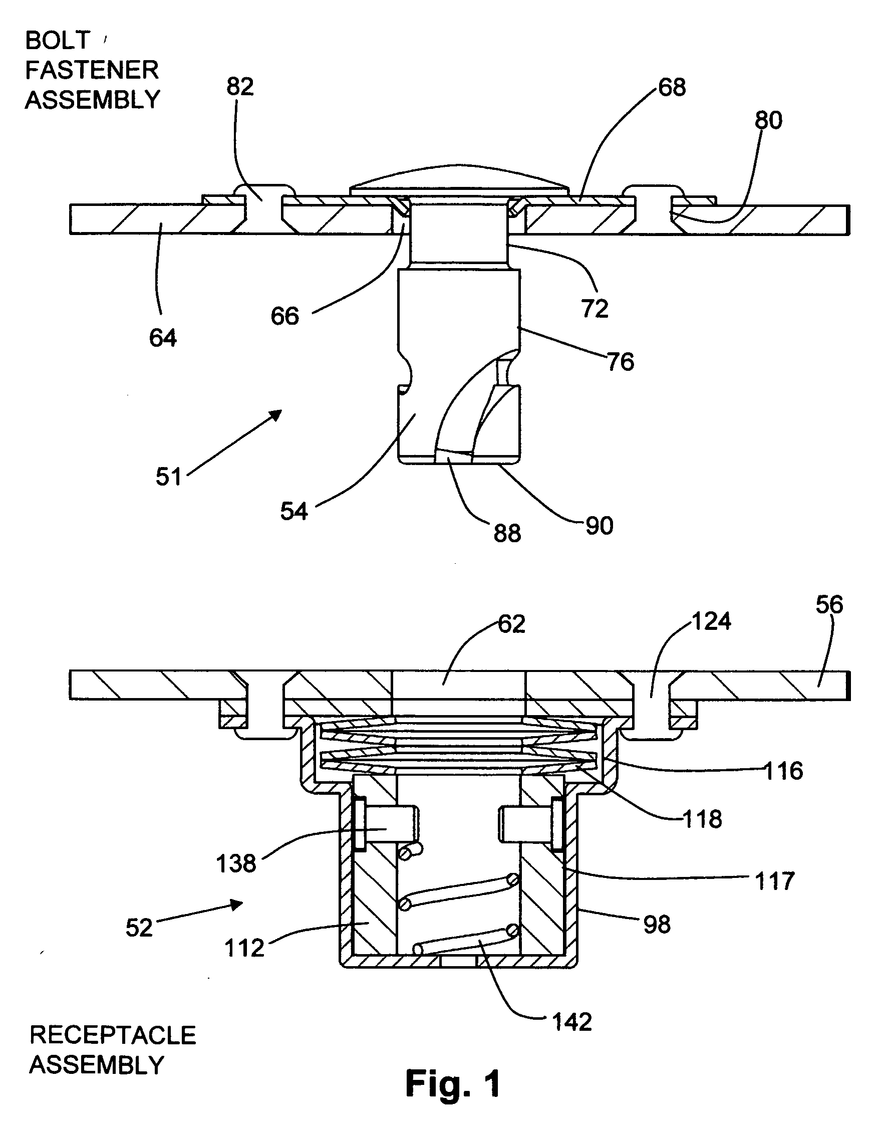
[0036]The high strength fastening system of the present disclosure in FIG. 1 and 2 includes a receptacle assembly 52 and a bolt fastener assembly 51.

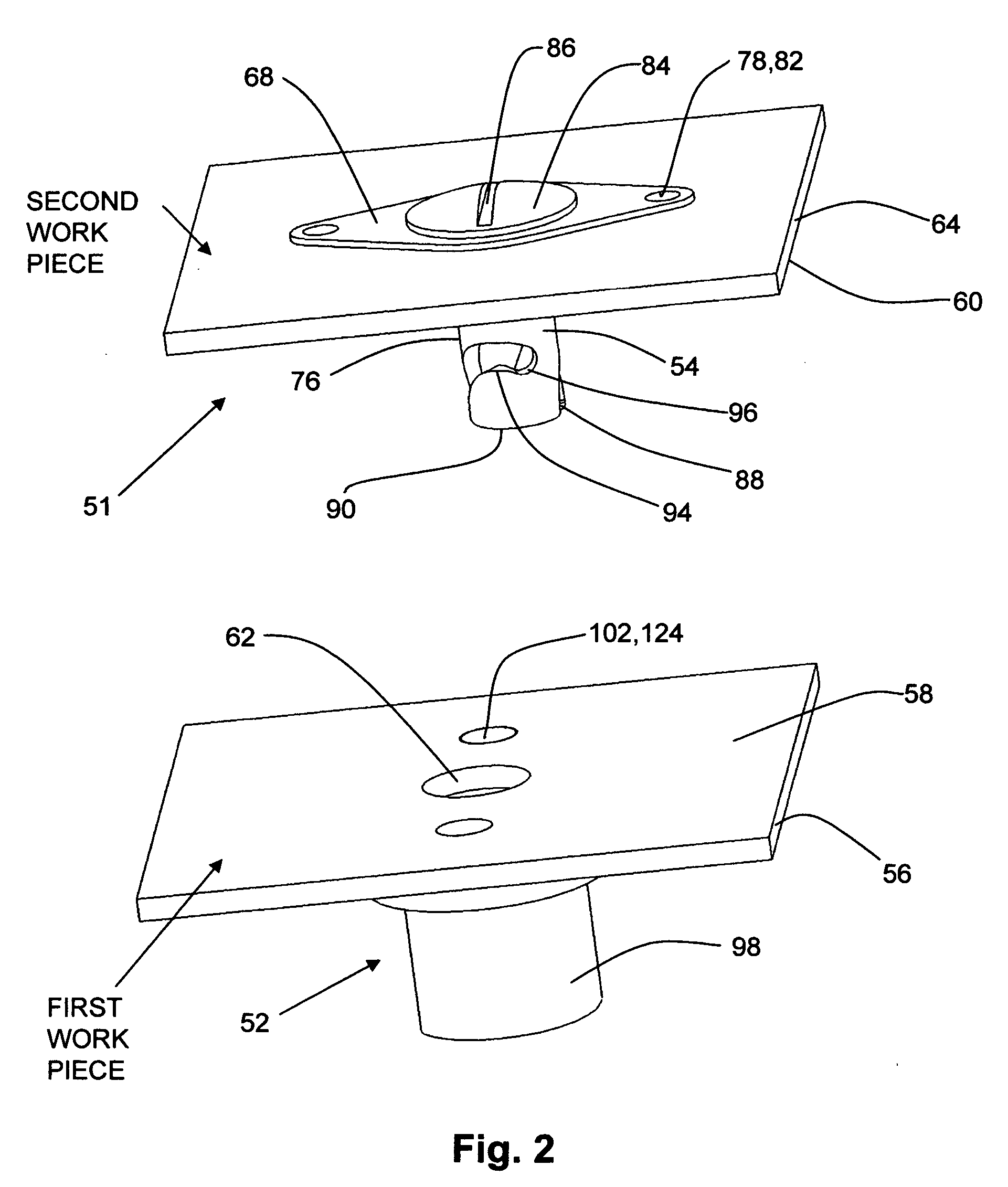
[0037]The receptacle assembly 52 is designed to be attached to the first work piece 56 such as a plate, having a flat surface around the fastener area 58 and a flat parallel surface on the other side of the first work piece. The first work piece 56 has a round bore 62. The bolt fastener 54 in FIG. 1, 2 is attached to a second work piece 64 which is a plate with 2 parallel surfaces. The bore 66FIG. 1, 7, is created to accommodate the bolt fastener 54 shown in FIGS. 1 and 7.

[0038]The bolt fastener 54 is secured into place by a retaining bracket 68 in FIG. 1, 7. This retaining bracket 68 has an aperture 70 in FIG. 7, which is less in diameter than the shank diameter 76 of the bolt fastener 54, and as the bolt fastener 54 has an incut 72FIG. 1, 7 which is smaller in diameter than the aperture 70FIG. 7 in the retaining bracket 68. The bolt f...


PUM


Abstract

A fastening system to press together 2 work pieces. These are plates with a circular aperture on each plate. The first work piece is engaged to the second work piece through a biased engagement. The receptacle assembly consists of a housing and its mechanical contents attached to the first work piece. The bolt assembly consists of a cylindrical bolt with a head and a shank attached and captured thru a retaining bracket to the second work piece and is moveable with respect to the receptacle assembly between the extended and retracted position. Two or more disc springs inside the housing bias the fastener toward the locked position with a biasing force. The bolt fastener has 2 opposing spiral cam slots machined on its shank and when introduced into the pin ring, inside the housing, will engage 2 radial placed cross-pins in its cam slots. Said cross-pins are seated in the pin ring. When the bolt fastener is rotated from the extended position to the retracted position it will lift the cross-pins and with it the pin ring against the disc springs and compressing them so as to provide a biasing force to press the first work piece in engagement with the second work piece.

Description

[0001]This application claims the benefit of provisional patent application Ser. No. U.S. 60 / 776,111, filed Feb. 23, 2006 by the present inventors.FEDERALLY SPONSORED RESEARCH [0002]Not applicableSEQUENCE LISTING OR PROGRAM [0003]Not applicableFIELD OF INVENTION [0004]FastenerReference cited:US patents:3,874,041Smith,19754,067,090Schenk19784,227,287Gunther19804,308,646Schenk19824,378,615Gunther19834,522,541Bidwell1985Pub. No.US 2005 / 0008458 A1Keech(abandoned)BACKGROUND OF THE INVENTION [0005]Quarter turn fasteners of the quick release type, are well known and have been in use for many years. The present disclosure overcomes some of the shortcomings with prior art fastening systems that include S-shaped coiled springs or helical springs which show in special applications fatigue limitations and limited resistance to vibrations, limited cycle time and limited G-forces. Previous designs show bolt fasteners having a hollow end and having two spiral cam slots on the shank of the bolt fas...

Claims


Application Information

Patent Timeline
IPC IPC(8): F16B21/00
CPCF16B21/04
Inventor SCHORLING, DETLEF T.KEECH, NANCY KAY
Owner SCHORLING DETLEF T
Why Eureka
Try Eureka