Method For Laser Machining And Laser Device With Laser Power Controlled As a Function Of The Laser Motion

a laser device and laser technology, applied in the direction of laser beam welding apparatus, manipulators, transportation and packaging, etc., can solve the problem of limited welding speed that can be reached with the prior-art technique, and achieve the effect of better laser welding techniqu

Inactive Publication Date: 2007-08-30
KUKA SYSTEMS
View PDF15 Cites 83 Cited by
  • Summary
  • Abstract
  • Description
  • Claims
  • Application Information

AI Technical Summary

Benefits of technology

[0007] The object of the present invention...

Problems solved by technology

Only limited welding speeds can be reached with the prior-art technique.
Another problem lies in the fact that the robot path ...

Method used


Image

  • Method For Laser Machining And Laser Device With Laser Power Controlled As a Function Of The Laser Motion
  • Method For Laser Machining And Laser Device With Laser Power Controlled As a Function Of The Laser Motion
  • Method For Laser Machining And Laser Device With Laser Power Controlled As a Function Of The Laser Motion

Examples


Embodiment Construction

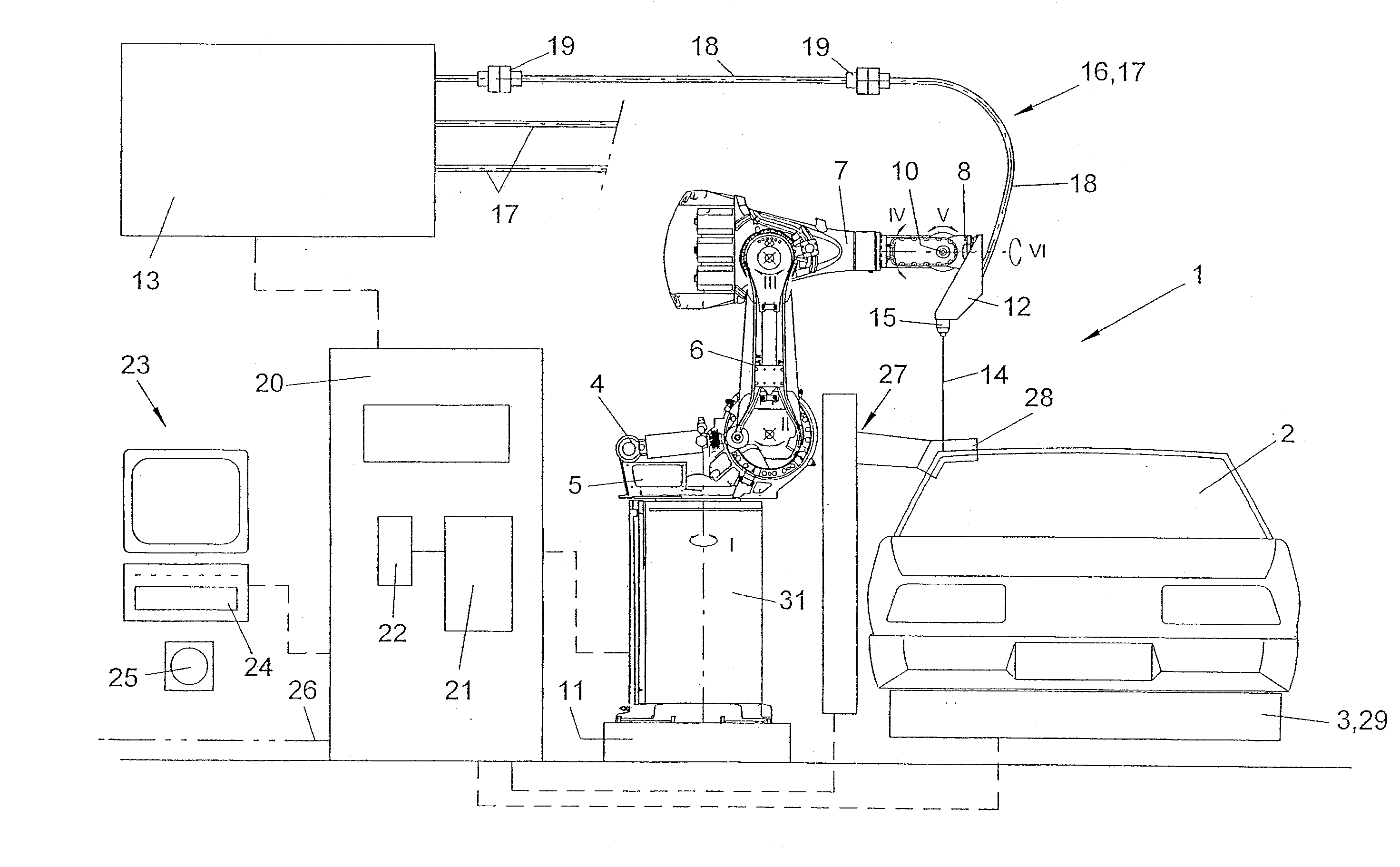
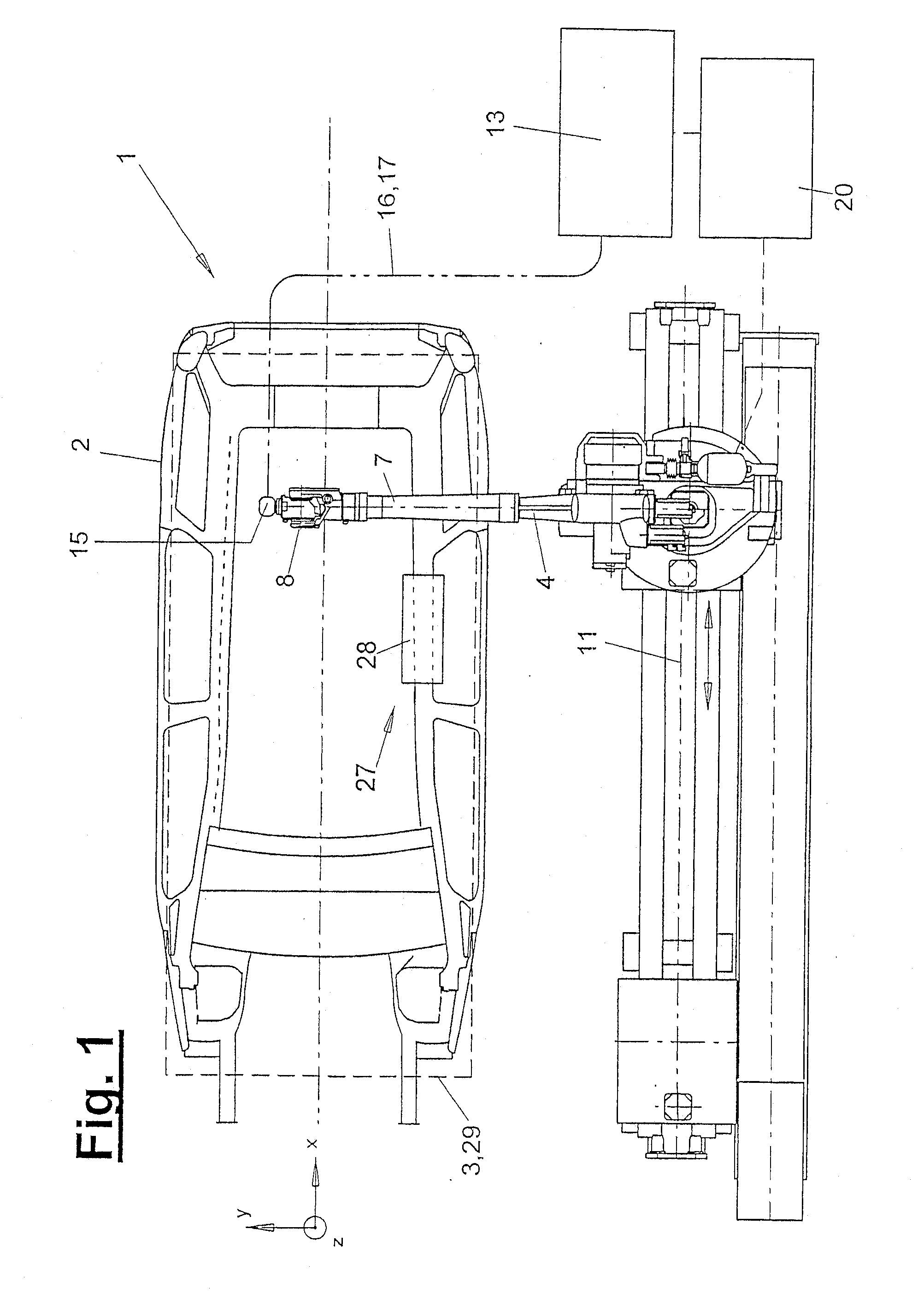
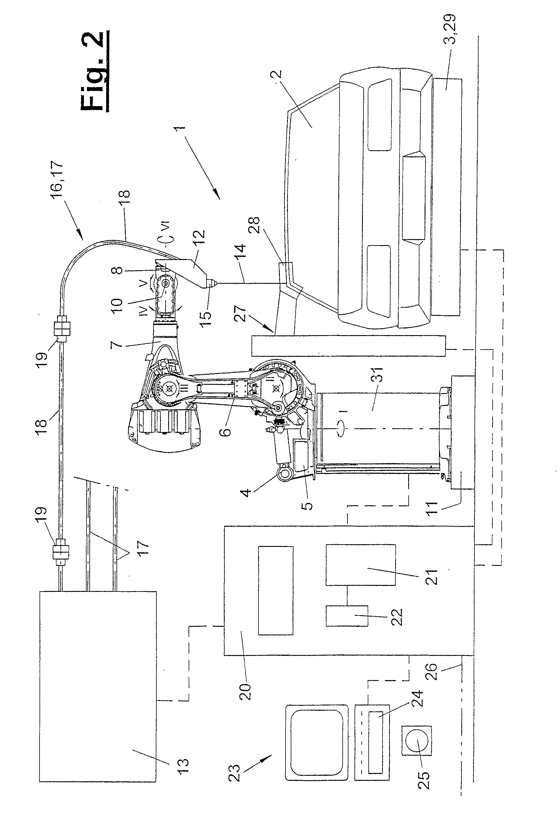
[0034] Referring to the drawings in particular, FIGS. 1 and 2 show side views and front views of the general design of a laser means (1) in a schematic top view. The laser means (1) may be part of a machining station in the form of an independent cell or station in a production line. Furthermore, a plurality of laser means (1) may be present in the station. In the embodiment being shown, it is, for example, a geo station or framing station in body framing and paneling, in which the initially loosely clamped body (2) receives its final shape. As an alternative, the station may also be designed as a weld deposit station or a respot station. Furthermore, use in production cells for body parts, e.g., side panels or the like, is also possible. In general, the laser means (1) can be used in any desired environment and used to machine any desired workpiece (2), the latter preferably being vehicles bodies or body parts thereof.

[0035] The laser means (1) comprises at least one manipulator (...


PUM

PropertyMeasurementUnit
Distanceaaaaaaaaaa
Lengthaaaaaaaaaa
Poweraaaaaaaaaa

Abstract

A method and device (1) for laser machining vehicle bodies or body parts (2) uses a laser beam (14) that is guided from a laser source (13) to a remote laser tool (15) on a robot hand by a guiding device (16). The robot (4) maintains the laser tool (15) in a suspended manner over the tool (2), at a focal length (F) and at a contact free distance and guides it along a machining path (30). The laser beam (14) is deviated, by movement of the hand axis (IV, V, VI), about a variable deviation angle (α), and the laser source (13), whose power is variable, is controlled according to the movement of the laser beam. The beam deviation of the hand axis (IV, V, VI) can be superimposed on an offset movement of the robot (4).

Description

CROSS REFERENCE TO RELATED APPLICATIONS [0001] This application is a United States National Phase application of International Application PCT / EP2005 / 002438 and claims the benefit of priority under 35 U.S.C. § 119 of German Priority 10 2004 011 769.1 filed Mar. 9, 2004, the entire contents of which are incorporated herein by reference.FIELD OF THE INVENTION [0002] The present invention pertains to a method for laser machining and to a laser device. BACKGROUND OF THE INVENTION [0003] Such a laser machining method along with a laser device for the laser welding of vehicle bodies is known from DE 103 35 501 A1. A laser beam is guided from a laser source via a guiding means to a remote laser tool at a multiaxial hand of a manipulator and directed towards a workpiece. The manipulator now moves the remote laser tool at a contact-free distance floatingly over the workpiece along a machining path. The laser beam can be deflected here via a scanner optical system integrated in the laser weld...

Claims


Application Information

Patent Timeline
IPC IPC(8): B23K26/08B23K26/04B23K26/10B23K26/20B25J19/00
CPCB23K26/04B23K2201/006B23K26/20B23K26/0884B23K26/26B23K26/28B23K2101/006
Inventor RIPPL, PETERHESSE, JOHANNENGLHARD, ANTON
Owner KUKA SYSTEMS
Why Eureka
Try Eureka