Apparatus for generating random numbers

a random number and apparatus technology, applied in the field of microelectronics, can solve the problem that there is no hardware technique or approach that lends itself to incorporation within the microprocessor circui

Inactive Publication Date: 2005-04-26
IP FIRST
View PDF6 Cites 18 Cited by
  • Summary
  • Abstract
  • Description
  • Claims
  • Application Information

AI Technical Summary

Benefits of technology

[0014]The present invention provides a superior technique hardware-based random number generation. In one embodiment, an apparatus for generating a random number is provided. The apparatus includes a first variable frequency oscillator, a second variable frequency oscillator, and frequency variation logic. The first variable frequency oscillator generates a first oscillatory signal at a first frequency. The second variable frequency oscillator generates a second oscillatory signal that is asynchronous to the first oscillatory signal and has a second frequency less than the first frequency. Bits of the random number are configured from samples of the first oscillatory signal taken at the second frequency. The frequency variation logic is coupled to the second variable frequency oscillator. The frequency variation logic generates a noise signal that directs the second variable frequency oscillator to vary the second frequency. The noise signal corresponds to parity of a third oscillatory signal and a fourth oscillatory signal, where the third and fourth oscillatory signals are asynchronous to each other and to the first and second oscillatory signals.
[0015]One aspect of the present invention contemplates a random number generation apparatus for use within an integrated circuit. The random number generation apparatus has a fast oscillator, a slow oscillator, domain synchronization logic, and frequency variation logic. The fast oscillator generates a fast oscillatory signal at a first frequency. The slow oscillator generates a slow oscillatory signal. The slow oscillatory signal is decoupled from the fast oscillatory signal and is at a second frequency that is less than half of the first frequency. The domain synchronization logic is coupled to the fast and slow oscillators. The domain synchronization logic samples the fast oscillatory signal in phase with the slow oscillatory signal to obtain potential bits for a random number. The frequency variation logic is coupled to the slow oscillator. The frequency variation logic varies the second frequency according to the parity of two independent oscillatory signals.
[0016]Another aspect of the present invention comprehends a random number generator within a microprocessor. The random number generator includes a slow oscillator, balance logic, and frequency variation logic. The slow oscillator produces a sampling clock signal, where the sampling clock signal is employed to obtain samples of a first oscillatory signal, and where the sampling clock signal runs at less than half the frequency of the first oscillatory signal. The balance logic is coupled to the slow oscillator. The balance logic rejects successive pairs of the samples that have the same state, and configures bits of a random number from the successive pairs of the samples that have different states. The frequency variation logic is coupled to the slow oscillator. The frequency variation logic varies the frequency of the sampling clock signal in accordance with the parity of two asynchronous oscillatory signals.

Problems solved by technology

Some hardware-based random number generators are available as separate integrated circuits, but to date, no hardware technique or approach exists that lends itself to incorporation within a microprocessor circuit.

Method used


Image

  • Apparatus for generating random numbers
  • Apparatus for generating random numbers
  • Apparatus for generating random numbers

Examples


Embodiment Construction

[0029]The following description is presented to enable one of ordinary skill in the art to make and use the present invention as provided within the context of a particular application and its requirements. Various modifications to the preferred embodiment will, however, be apparent to one skilled in the art, and the general principles defined herein may be applied to other embodiments. Therefore, the present invention is not intended to be limited to the particular embodiments shown and described herein, but is to be accorded the widest scope consistent with the principles and novel features herein disclosed.

[0030]In view of the above background discussion on random number generation and associated techniques employed within present day integrated circuits for the generation of random numbers, a discussion of the present invention will now be presented with reference to FIGS. 1-11.

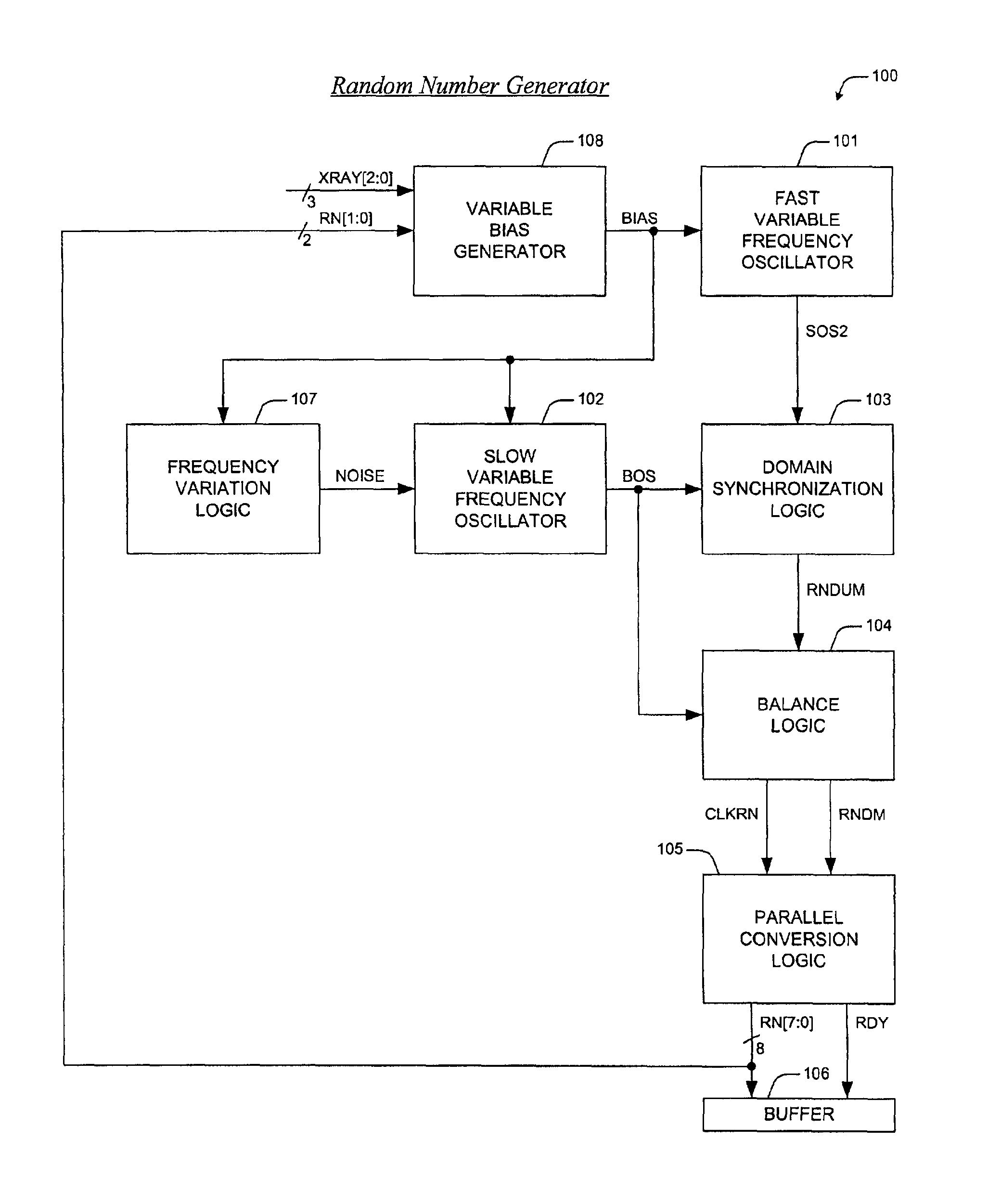
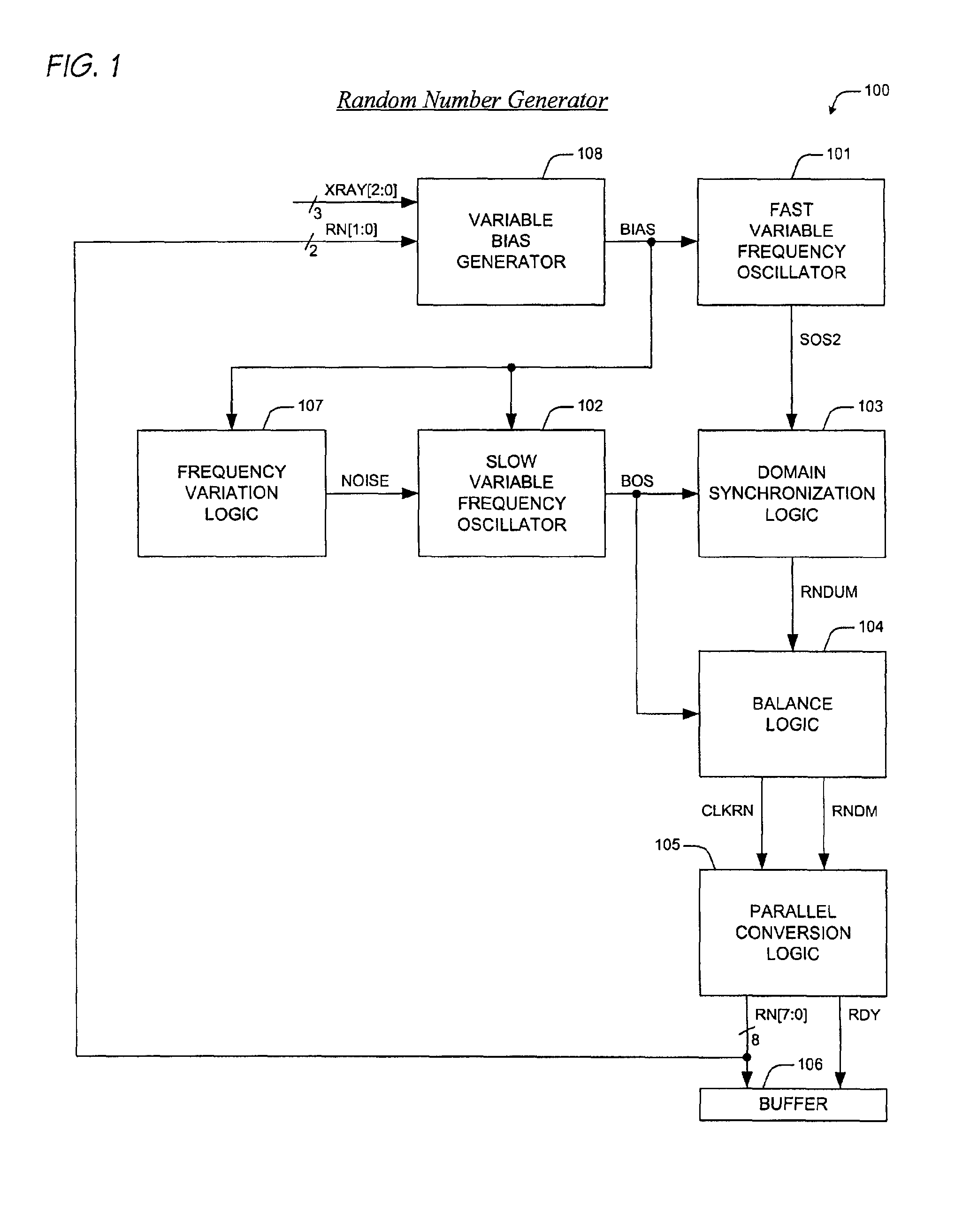
[0031]Turning to FIG. 1, a block diagram is presented illustrating an apparatus for generating random ...


PUM


Abstract

A hardware-based random number generator is provided for incorporation within an integrated circuit. The random number generator includes a first variable frequency oscillator, a second variable frequency oscillator, and frequency variation logic. The first variable frequency oscillator generates a first oscillatory signal at a first frequency. The second variable frequency oscillator generates a second oscillatory signal that is asynchronous to the first oscillatory signal and has a second frequency less than the first frequency. Bits of the random number are configured from samples of the first oscillatory signal taken at the second frequency. The frequency variation logic is coupled to the second variable frequency oscillator. The frequency variation logic generates a noise signal that directs the second variable frequency oscillator to vary the second frequency. The noise signal corresponds to parity of a third oscillatory signal and a fourth oscillatory signal, where the third and fourth oscillatory signals are asynchronous to each other and to the first and second oscillatory signals.

Description

CROSS-REFERENCE TO RELATED APPLICATIONS[0001]This application is related to the following co-pending U.S. Patent Applications, which are filed on the same day as this application, and which have a common assignee and common inventors.[0002]SERIALFILINGNUMBERDATETITLE10 / 046054Jan. 14, 2002OSCILLATOR BIAS VARIATION(CNTR.2155)MECHANISM10 / 046057Jan. 14, 2002OSCILLATOR FREQUENCY(CNTR.2156)VARIATION MECHANISMBACKGROUND OF THE INVENTION[0003]1. Field of the Invention[0004]This invention relates in general to the field of microelectronics, and more particularly to a random number generation apparatus for use within an integrated circuit.[0005]2. Description of the Related Art[0006]Many present day computer-based applications rely heavily on the availability of random numbers. What has historically been the province of scientific programmers has more recently crept over into the commercial realm.[0007]In prior years, large and powerful computing systems utilized random numbers for use within...

Claims


Application Information

Patent Timeline
Patent Type & Authority Patents(United States)
IPC IPC(8): G06F7/58G06F1/02G06F7/556G06F7/48
CPCG06F7/588
Inventor LUNDBERG, JAMES R.
Owner IP FIRST
Why Eureka
Try Eureka