Apparatus and method for demand coordination network control

a demand coordination and network control technology, applied in the field of resource management, can solve the problems of limited supply and demand infrastructure, limited delivery and transport infrastructure, and variability in generation and consumption of resources with respect to tim

Active Publication Date: 2016-10-06
ENEL X NORTH AMERICA INC
View PDF5 Cites 22 Cited by
  • Summary
  • Abstract
  • Description
  • Claims
  • Application Information

AI Technical Summary

Benefits of technology

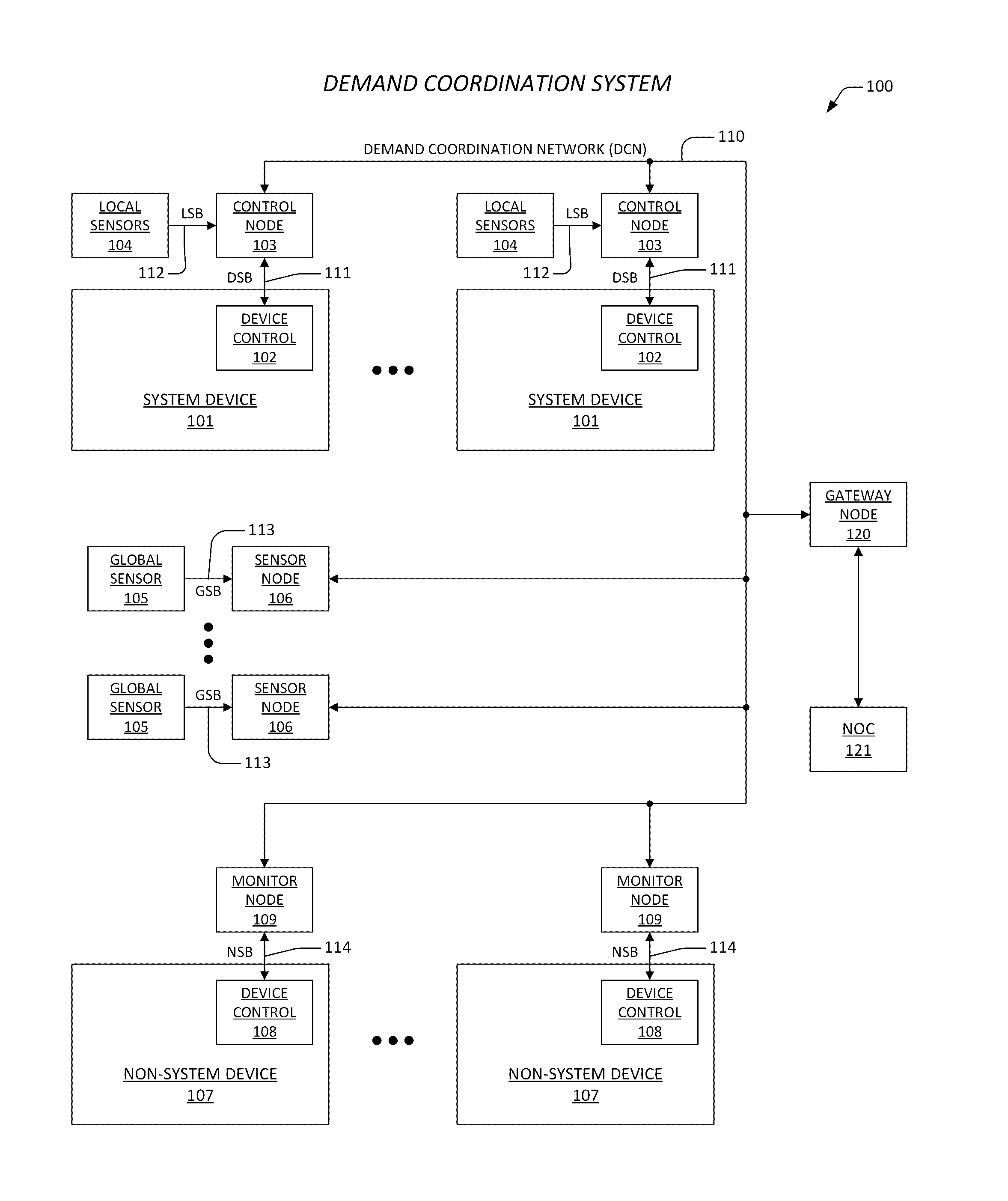
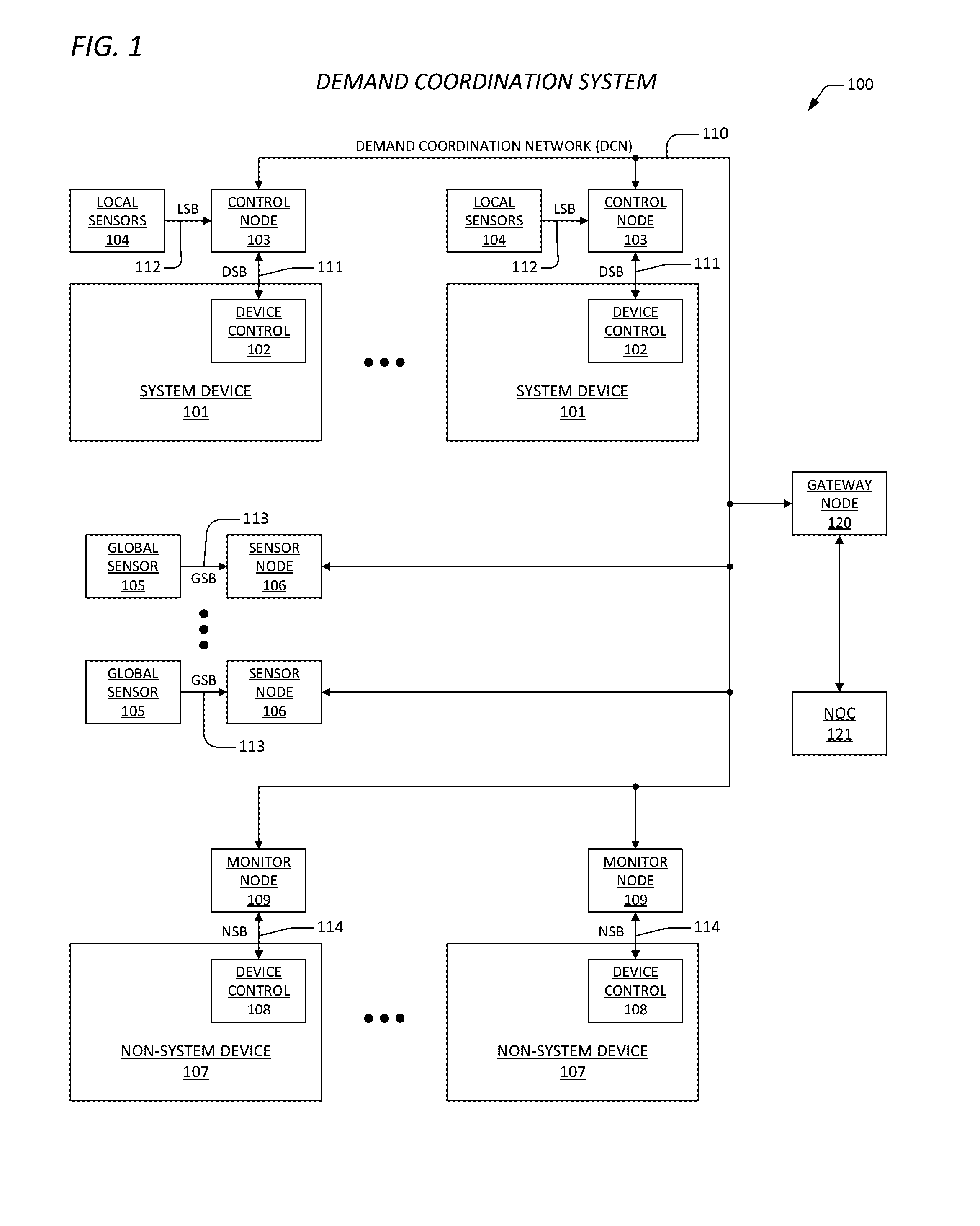
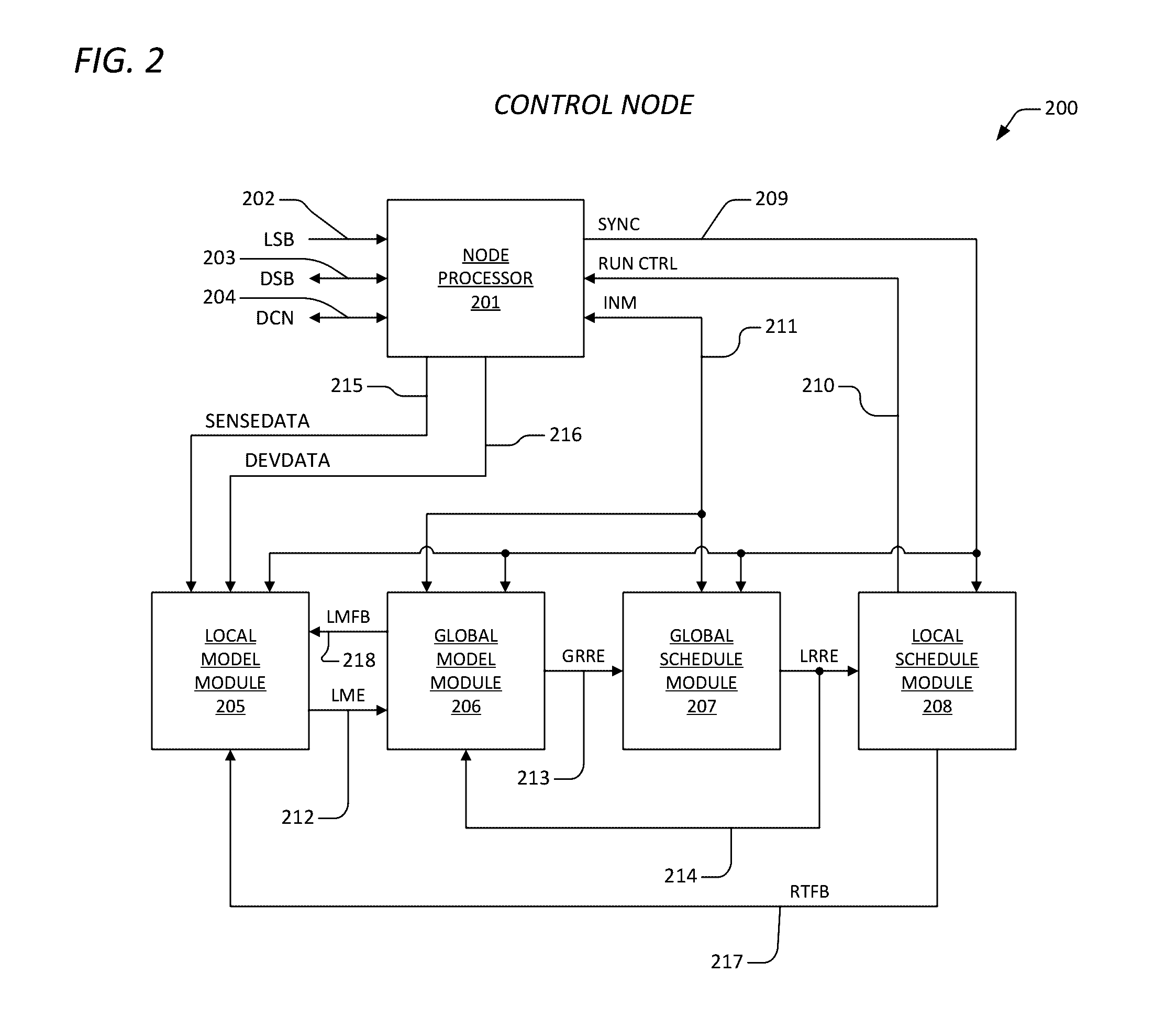
[0017]The present invention, among other applications, is directed to solving the above-noted problems and addresses other problems, disadvantages, and limitations of the prior art. The present invention provides a superior technique for managing and controlling the demand level of a given resource as that resource is consumed by a plurality of consuming devices. In one embodiment, an apparatus for controlling peak demand of a resource within a facility. The apparatus includes a plurality of devices, a network operations center (NOC), and a plurality of control nodes. The plurality of devices is disposed within the facility, and each consumes a portion of the resource when turned on, and each is capable of performing a corresponding function within an acceptable operational margin by cycling on and off. The NOC is disposed external to the facility, and is configured to determine an energy lag for the facility based upon fine-grained energy consumption baseline data, and is configured to employ said energy lag to generate a plurality of run time schedules. The plurality of run time schedules coordinates run times for the each of the plurality of devices to control the peak demand of the resource. One or more of the run times start prior to when otherwise required to maintain corresponding local environments while operating within corresponding acceptable operating margins. The plurality of control nodes is disposed within the facility, and each is coupled to a corresponding one of the plurality of devices. The plurality of control nodes is coupled together via a demand coordination network that is operatively coupled to the NOC. The plurality of control nodes transmits sensor data and device status to the NOC via the demand coordination network for generation of the plurality of run time schedules, and the plurality of control nodes executes selected ones of the run time schedules to cycle the plurality of devices on and off.
[0018]One aspect of the present invention contemplates a peak demand control system, for managing peak energy demand within a facility. The peak demand control system has a network operations center (NOC), a plurality of control nodes, and one or more sensor nodes. The NOC is disposed external to the facility, and is configured to determine an energy lag for the facility based upon fine-grained energy consumption baseline data, and configured to employ said energy lag to generate a plurality of run time schedules, where the plurality of run time schedules coordinates run times for each of a plurality of devices to manage the peak energy demand, and where one or more of the run times start prior to when otherwise required to maintain corresponding local environments while operating within corresponding acceptable operating margins. The plurality of control nodes is disposed within the facility. Each is coupled to a corresponding one of the plurality of devices, where the plurality of control nodes are coupled together via a demand coordination network and operatively coupled to the NOC, and where the plurality of control nodes transmits sensor data and device status to the NOC via the demand coordination network for generation of the plurality of run time schedules, and where the plurality of control nodes executes selected ones of the run time schedules to cycle the plurality of devices on and off. The one or more sensor nodes are coupled to the demand coordination network, and are configured to provide one or more global sensor data sets to the NOC, where the NOC employs the one or more global sensor data sets in determining the run times.
[0019]Another aspect of the present invention comprehends a method for controlling peak demand of a resource within a facility. The method includes: via a network operations center (NOC) external to the facility, determining an energy lag for the facility based upon fine-grained energy consumption baseline data, and employing the energy lag to generate a plurality of run time schedules, where the plurality of run time schedules coordinates run times for each of a plurality of devices to control the peak demand of the resource, and where one or more of the run times start prior to when otherwise required to maintain corresponding local environments while operating within corresponding acceptable operating margins; controlling each of the plurality of devices via corresponding control nodes, where the each of the plurality of devices consumes a portion of the resource when turned on, and where the each of the plurality of devices is capable of performing a corresponding function within an acceptable operational margin by cycling on and off, and where the corresponding control nodes execute selected ones of the plurality of run time schedules to cycle the plurality of devices on and off; and first coupling the corresponding control nodes together via a demand coordination network that is operatively coupled to the NOC, and employing the demand coordination network to transmit sensor data and device status to the NOC for generation of the plurality of run time schedules.

Problems solved by technology

The problem with resources such as electrical power, water, fossil fuels, and their derivatives (e.g., natural gas) is that the generation and consumption of a resource both vary with respect to time.
Furthermore, the delivery and transport infrastructure is limited in that it cannot instantaneously match generation levels to provide for consumption levels.
The delivery and transport infrastructure is limited in supply and the demand for this limited supply is constantly fluctuating.
There are very simple ways to stagger run times, and there are very complicated mechanisms that are employed to lower peak demand, but they all utilize variations of what is known in the art as deferral.
What this means in the air conditioning example above is that some occupants are going to experience discomfort while waiting for their turn to run.
When duty cycles are reduced to defer demand, everyone in the facility is going to experience mild discomfort.
But the present inventors have observed that conventional techniques for controlling peak demand all involve delaying (“deferring”) the start times and durations of devices and / or decreasing the duty cycles, thus in many instances causing local environments to operate outside of their acceptable operational margins.
It is either too hot, too cold, not enough water, the motors are not running long enough to get the job done, and etc.
Furthermore, these conventional techniques do not take into account the energy lag of a building, that is, the transient response of the building's energy consumption in response to changes in outside temperature.

Method used


Image

  • Apparatus and method for demand coordination network control
  • Apparatus and method for demand coordination network control
  • Apparatus and method for demand coordination network control

Examples


Embodiment Construction

[0036]Exemplary and illustrative embodiments of the invention are described below. In the interest of clarity, not all features of an actual implementation are described in this specification, for those skilled in the art will appreciate that in the development of any such actual embodiment, numerous implementation-specific decisions are made to achieve specific goals, such as compliance with system related and / or business related constraints, which vary from one implementation to another. Furthermore, it will be appreciated that such a development effort might be complex and time-consuming, but would nevertheless be a routine undertaking for those of ordinary skill in the art having the benefit of this disclosure. Various modifications to the preferred embodiment will be apparent to those skilled in the art, and the general principles defined herein may be applied to other embodiments. Therefore, the present invention is not intended to be limited to the particular embodiments show...


PUM


Abstract

An apparatus including devices, a network operations center (NOC), and control nodes. Each of the devices consumes a portion of a resource when turned on, and performs a corresponding function within an acceptable operational margin by cycling on and off. The NOC is disposed external to a facility, and determines an energy lag for the facility based upon fine-grained energy consumption baseline data. The NOC employs the energy lag to generate a plurality of run time schedules that coordinates run times for the each of the devices to control the peak demand of the resource. Each of the plurality of control nodes is coupled to a corresponding one of the plurality of devices. The plurality of control nodes transmits sensor data and device status to the NOC via the demand coordination network for generation of the plurality of run time schedules, and executes selected ones of the run time schedules to cycle the plurality of devices on and off.

Description

CROSS-REFERENCE TO RELATED APPLICATIONS[0001]This application is related to the following co-pending U.S. patent applications, each of which has a common assignee and common inventors.SER.FILINGNO.DATETITLE      —APPARATUS AND METHOD FOR FINE-GRAINED(ENER.0127)WEATHER NORMALIZATION OF ENERGYCONSUMPTION BASELINE DATA      —SYSTEM FOR WEATHER INDUCED FACILITY ENERGY(ENER.0131)CONSUMPTION CHARACTERIZATION      —DEMAND RESPONSE DISPATCH SYSTEM(ENER.0132)EMPLOYING WEATHER INDUCED FACILITY ENERGYCONSUMPTION CHARACTERIZATIONS      —DEMAND RESPONSE DISPATCH PREDICTION(ENER.0133)SYSTEM      —ENERGY BROWN OUT PREDICTION SYSTEM(ENER.0134)BACKGROUND OF THE INVENTION[0002]1. Field of the Invention[0003]This invention relates in general to the field of resource management, and more particularly to an off-site apparatus and method employing fine-grained weather normalization of energy consumption baseline data for coordinating the use of certain resources in a demand coordination network such that...

Claims


Application Information

Patent Timeline
Patent Type & Authority Applications(United States)
IPC IPC(8): G05B19/048G05B19/10
CPCG05B19/048G05B2219/2639G05B19/106G06Q50/00
Inventor AL-MOHSSEN, HUSAINBASSA, ANGELA S.PARADIS, RICHARD R.WILLIG, RANDY C.
Owner ENEL X NORTH AMERICA INC
Why Eureka
Try Eureka