
Techniques for depositing transparent conductive oxide coatings using dual C-MAG sputter apparatuses
a technology of transparent conductive oxide and sputtering apparatus, which is applied in the direction of coating, vacuum evaporation coating, electrolysis components, etc., can solve the problems of c-mag availability, difficult to obtain reactive sputtering, and difficult to deposit transparent conductive oxide (tco) films, etc., to achieve stable and controllable process and superior coating techniques
- Summary
- Abstract
- Description
- Claims
- Application Information
AI Technical Summary
Benefits of technology
Problems solved by technology
Method used
Image


Examples
example
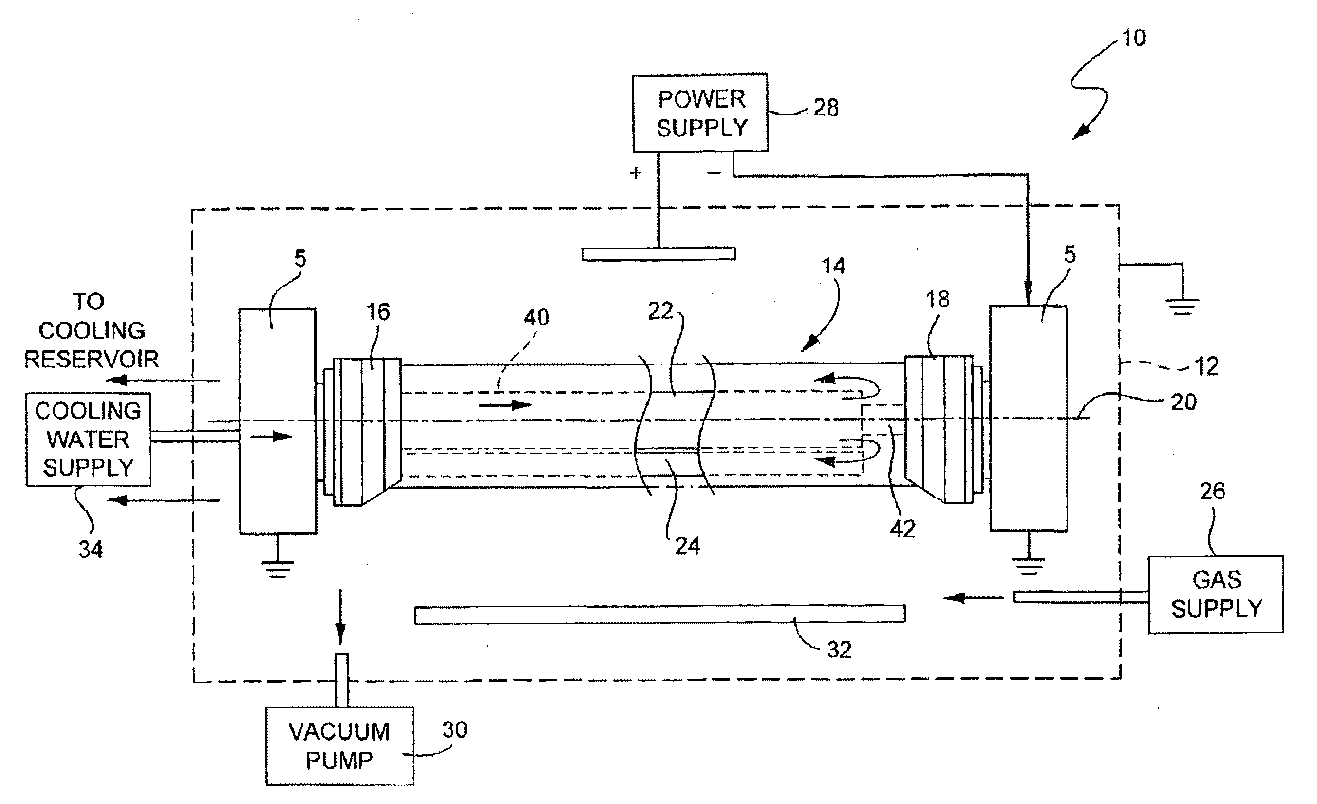
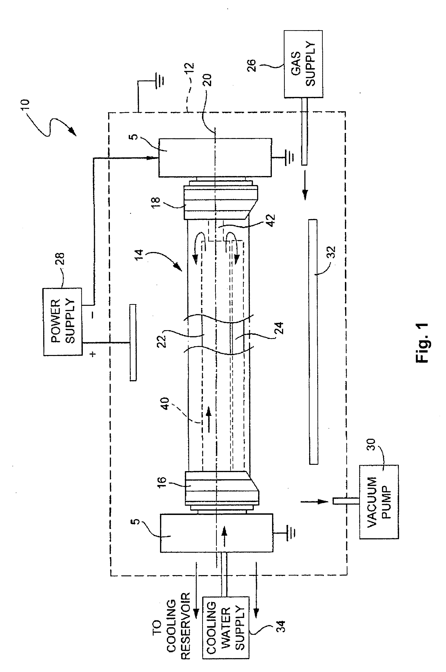
[0058]Lambda sensors / controllers were integrated into dual C-MAG sputtering apparatuses in certain example embodiments, which involved making hardware and software modifications for two test coating zones. As alluded to above, one or both of the coat zones of certain example embodiments may be configured to perform closed-loop control of power, gas flow, and / or the combination of power and gas flow, e.g., during the deposition of metal oxides, in conjunction with the Lambda sensor / controller. For example, a first coat zone may be used to deposit ITO using both power and combination of power and gas flow control modes, whereas a second coat zone may be used to deposit ZnAlOx using the power control mode.
[0059]Various ITO process parameters were developed for use in the first coat zone in certain example embodiments. It was possible to achieve an ITO coating using 25 kW power, 1 m / min line speed, and 600 sccm Ar flow. The ITO was about 100 nm thick and had a cross ribbon absorption lo...
example optimization
of Single Layer ITO Deposition Process
[0065]Described below are the results of one example ITO optimization process. In brief, it was possible to obtain ITO films with a resistivity around 1 mOhm-cm with absorption levels at 3-5%. Using trim oxygen gas to balance thickness uniformity resulted in a systematic thickness peak in the center of the lite. This peak was about 7-10% higher than the outlying areas and was accompanied by an increase in absorption, indicating a deficit of oxygen in the center area. Further improvements may be possible when using a more dedicated way to adjust the trim gas, as discussed in greater detail below. It will be appreciated that the coating's surface thickness preferably varies less than about 10%, more preferably less than about 7%, still more preferably less than about 5%.
[0066]Absorption across the sheet (e.g., 100-YT-YRF) turns out to be a parameter closely correlated with thickness variations and thus may be used as a quick guide to adjust unifor...
PUM
| Property | Measurement | Unit |
|---|---|---|
| frequency | aaaaa | aaaaa |
| height | aaaaa | aaaaa |
| thick | aaaaa | aaaaa |
Abstract
Description
Claims
Application Information