Luminous element

a technology of luminous elements and luminous tubes, which is applied in the field of luminous elements, can solve the problems of enlarge the dimensions of light sources, reduce the efficiency of light sources, so as to achieve the effect of saving energy

Inactive Publication Date: 2007-08-30
SCHOTT AG
View PDF10 Cites 127 Cited by
  • Summary
  • Abstract
  • Description
  • Claims
  • Application Information

AI Technical Summary

Benefits of technology

[0008] It is the object of the invention to provide an energy saving luminous element with small dimensions of the light source. This object is already provided in a surprisingly simple way by a luminous element in accordance with the present disclosure.

Problems solved by technology

However, these light sources have a few disadvantages.
Fluorescent tubes and lamps are relatively voluminous and are therefore not well suited for producing flat luminous elements.
In order to achieve a uniform illumination, there is a need to use a large number of closely neighbouring light-emitting diodes or optical fibres, and this correspondingly renders the luminous elements more expensive and enlarges the dimensions of the light source.

Method used


Image

  • Luminous element
  • Luminous element
  • Luminous element

Examples


Embodiment Construction

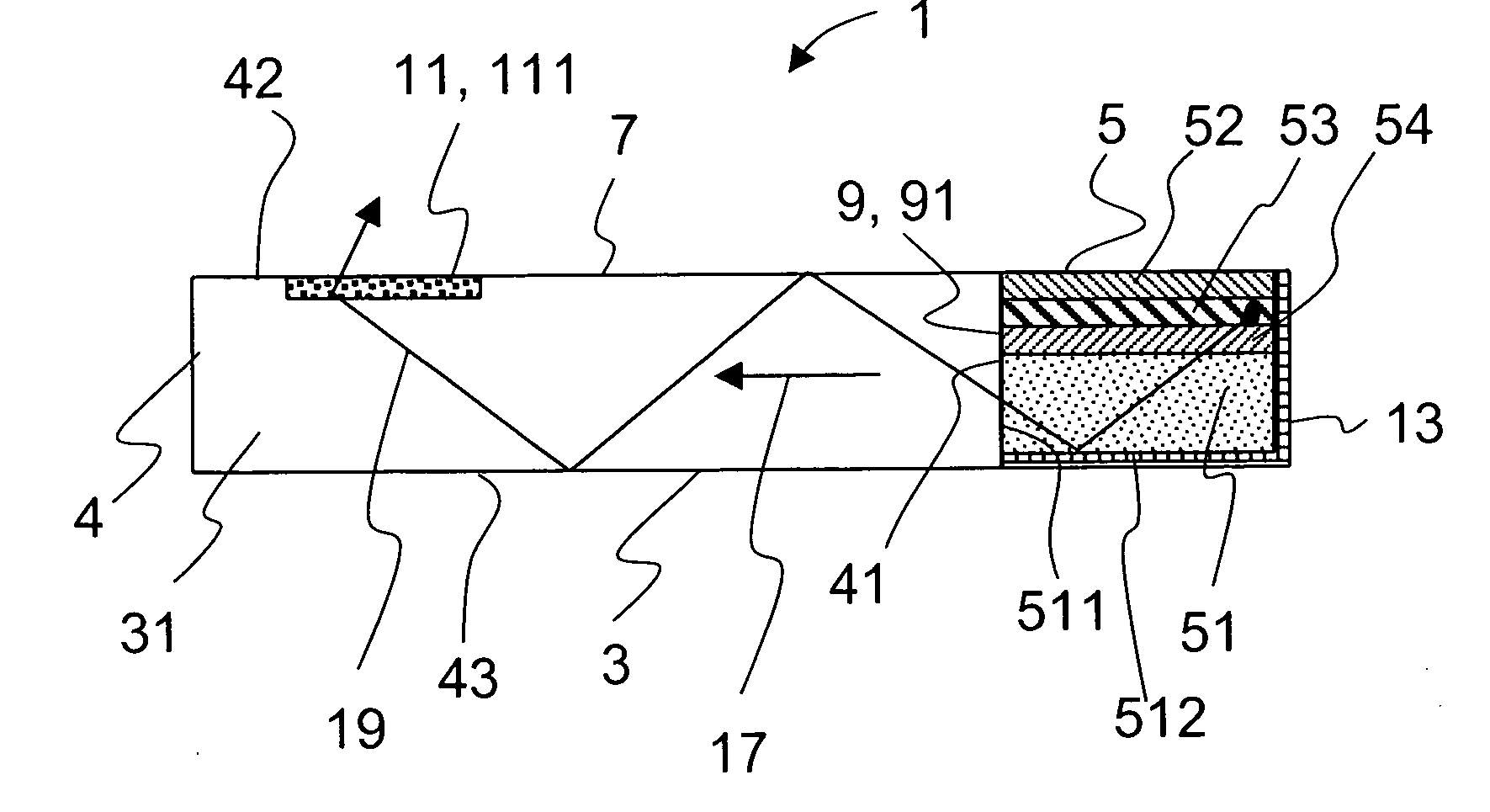
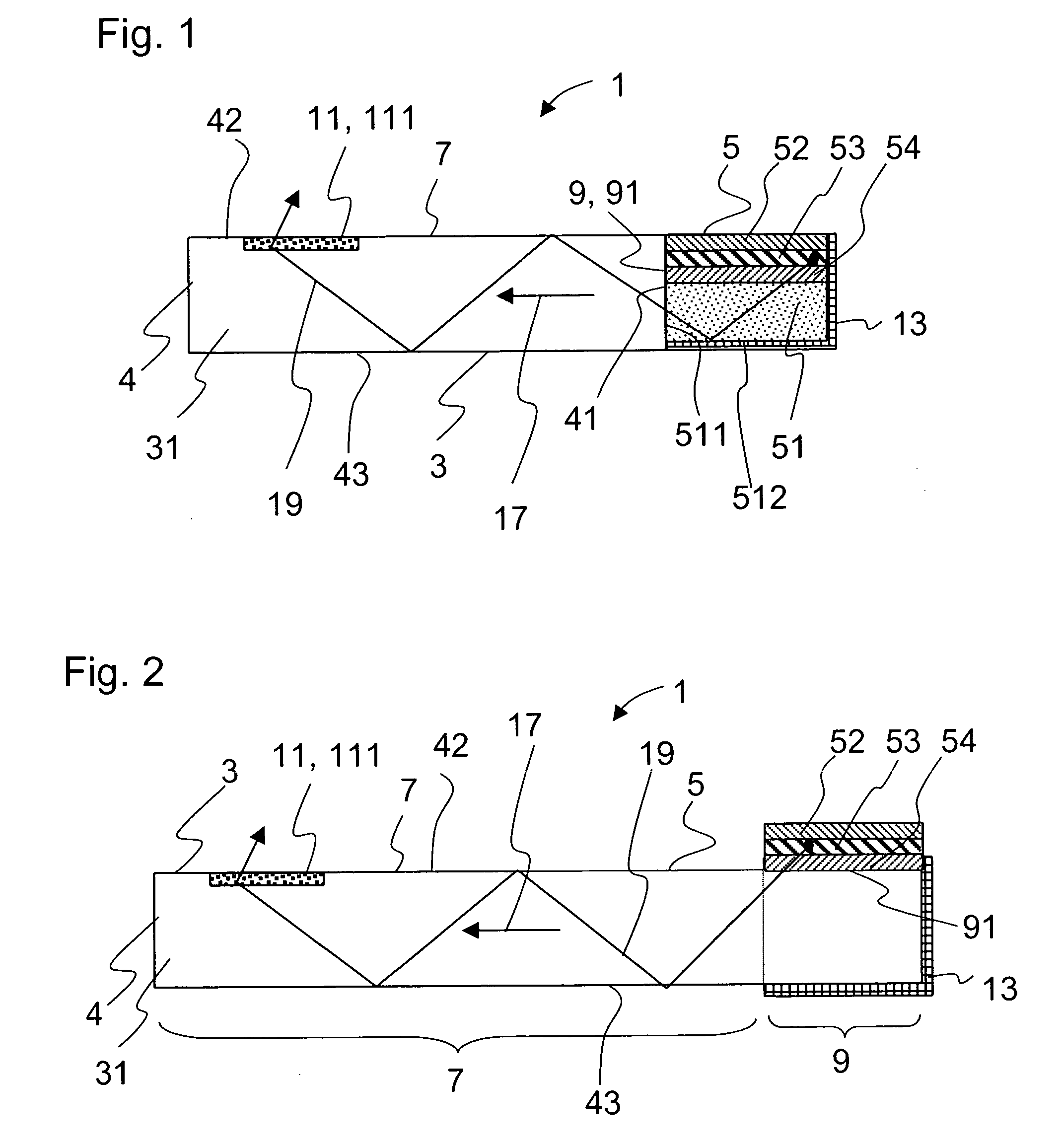
[0058]FIG. 1 illustrates a schematic sectional view through a first embodiment of a luminous element according to the invention which is denoted as a whole by the reference numeral 1.

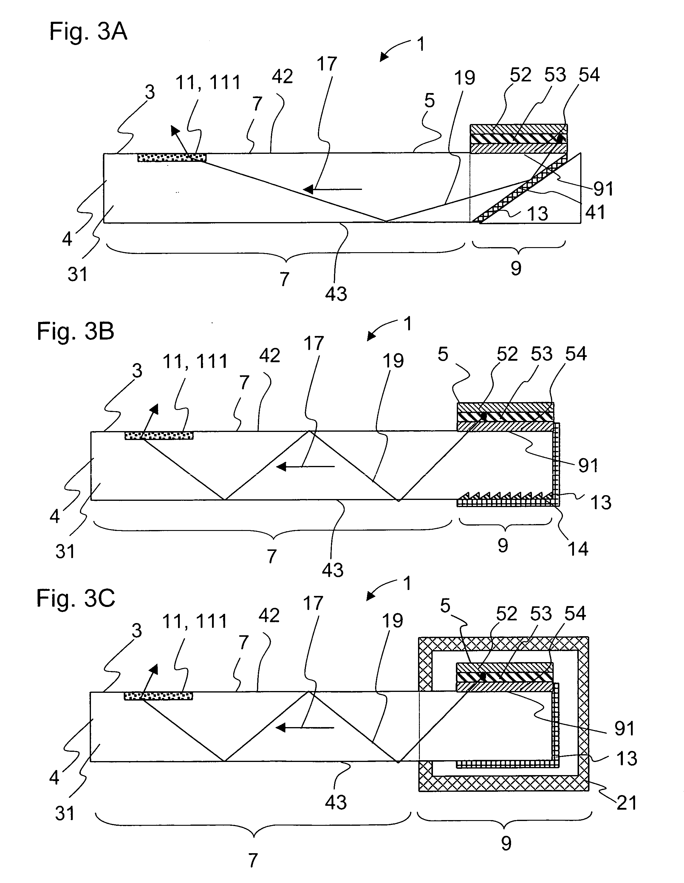
[0059] The luminous element 1 comprises a light-guiding device 3 in which light is guided by reflection. The light-guiding device 3 has a light-scattering area 7 and a light entry area 9 with a light entry surface 91. The light-guiding device 3 comprises a light guiding plate 4 with sides 42, 43 and narrow edge surfaces or lateral edges 41. In this embodiment, the light entry surface 91 is arranged at an edge surface 41 of the light guiding plate 4. It is also advantageously possible to use a film instead of a plate 4.

[0060] An OLED denoted as a whole by 5 is coupled to the light entry surface 91. In this embodiment, the OLED comprises a transparent substrate 51, for example made from glass, to which the OLED layers 52, 53 and 54 are applied.

[0061] The layers 52 and 54 are electrode layers for supply...


PUM


Abstract

The invention provides a luminous element that includes a light-guiding device in which light is guided by reflection. The light-guiding device has at least one light-scattering area with light-scattering structures. The light-scattering structures can be applied to the surface of the light-scattering area. The luminous element also includes at least one light entry surface that is coupled to at least one organic light-emitting diode.

Description

CROSS-REFERENCE TO RELATED APPLICATIONS [0001] This application claims the benefit under 35 U.S.C. 35 U.S.C. §365 of International Application Serial No. PCT / EP2004 / 008047, filed Jul. 21, 2003, the entire contents of which are incorporated by reference herein.BACKGROUND OF THE INVENTION [0002] 1. Field of the Invention [0003] The invention relates to a luminous element, in particular a luminous element with an optical waveguide. [0004] 2. Description of Related Art [0005] Luminous elements with light guiding plates are known from the prior art. Light is coupled into the plate and passed on in the plate by total reflection. The light is scattered or coupled out at disturbances, deliberately introduced into the light guiding plate, such as, for example, diffuse scattering centres or sharp contours, such as, for example, at milled indentations. Diffuse luminous surfaces or patterned luminous structures such as, for example, graphic characters have been produced in this way. [0006] Such...

Claims


Application Information

Patent Timeline
Patent Type & Authority Applications(United States)
IPC IPC(8): F21V7/00F21V8/00G02B5/12G02B6/00H01L51/10H01L51/52
CPCG02B6/0016G02B6/0018G02B6/002G02B6/0028H01L51/5271G02B6/0038G02B6/0061G02B6/0073H01L51/5268G02B6/0036H10K50/854H10K50/856
Inventor OTTERMANN, CLEMENS
Owner SCHOTT AG
Why Eureka
Try Eureka