Speaker System

Active Publication Date: 2007-08-30
SOVEREIGN PEAK VENTURES LLC
View PDF3 Cites 64 Cited by
  • Summary
  • Abstract
  • Description
  • Claims
  • Application Information

AI Technical Summary

Benefits of technology

[0043] According to the present invention, it is possible to achieve a speaker system and a video audio apparatus in which a distortion caused by a supporting sy

Problems solved by technology

Since passive radiators do not have a drive system including a voice coil, a magnetic circuit and the like, unlik

Method used


Image

  • Speaker System
  • Speaker System
  • Speaker System

Examples


embodiment 1

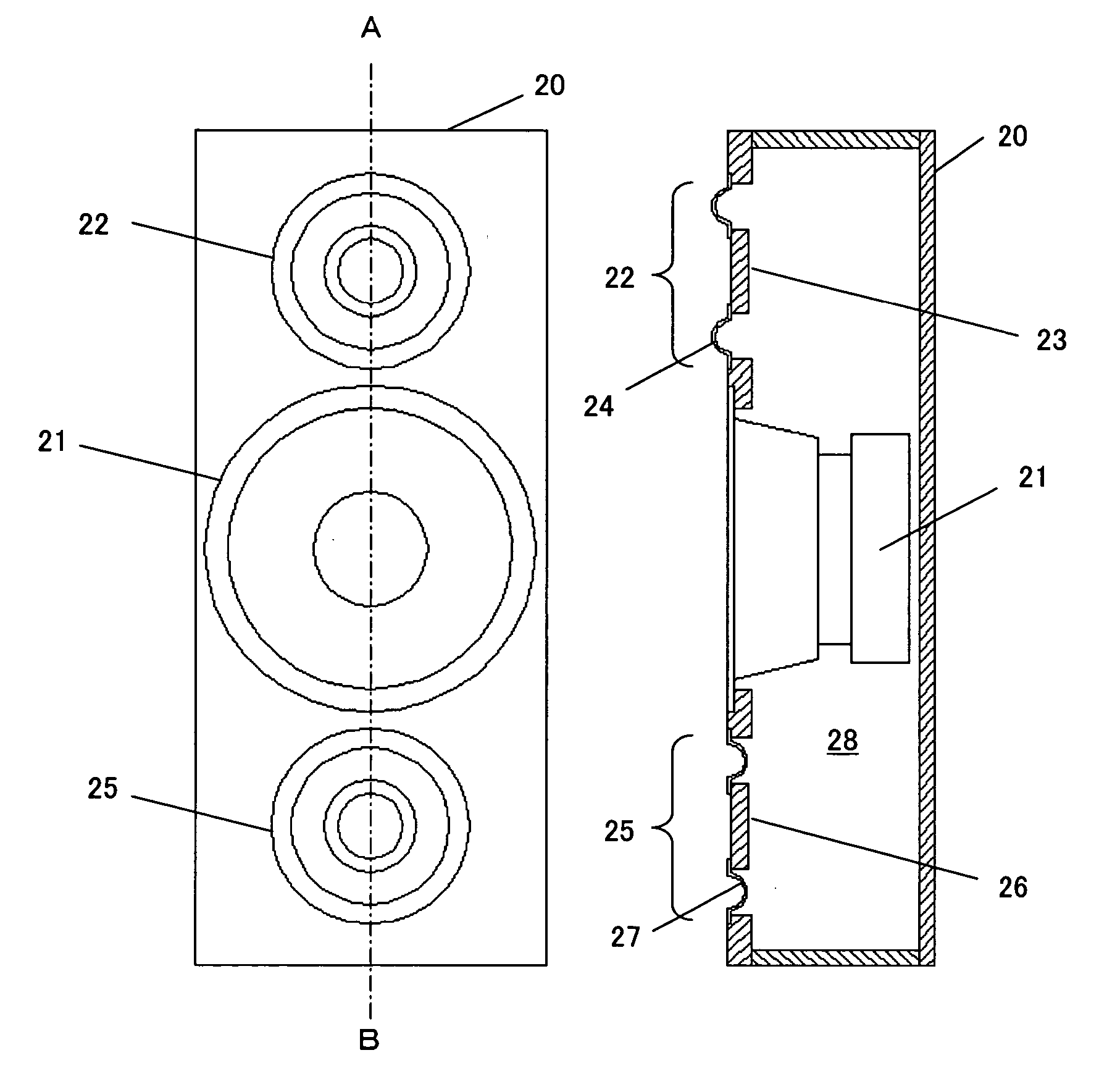
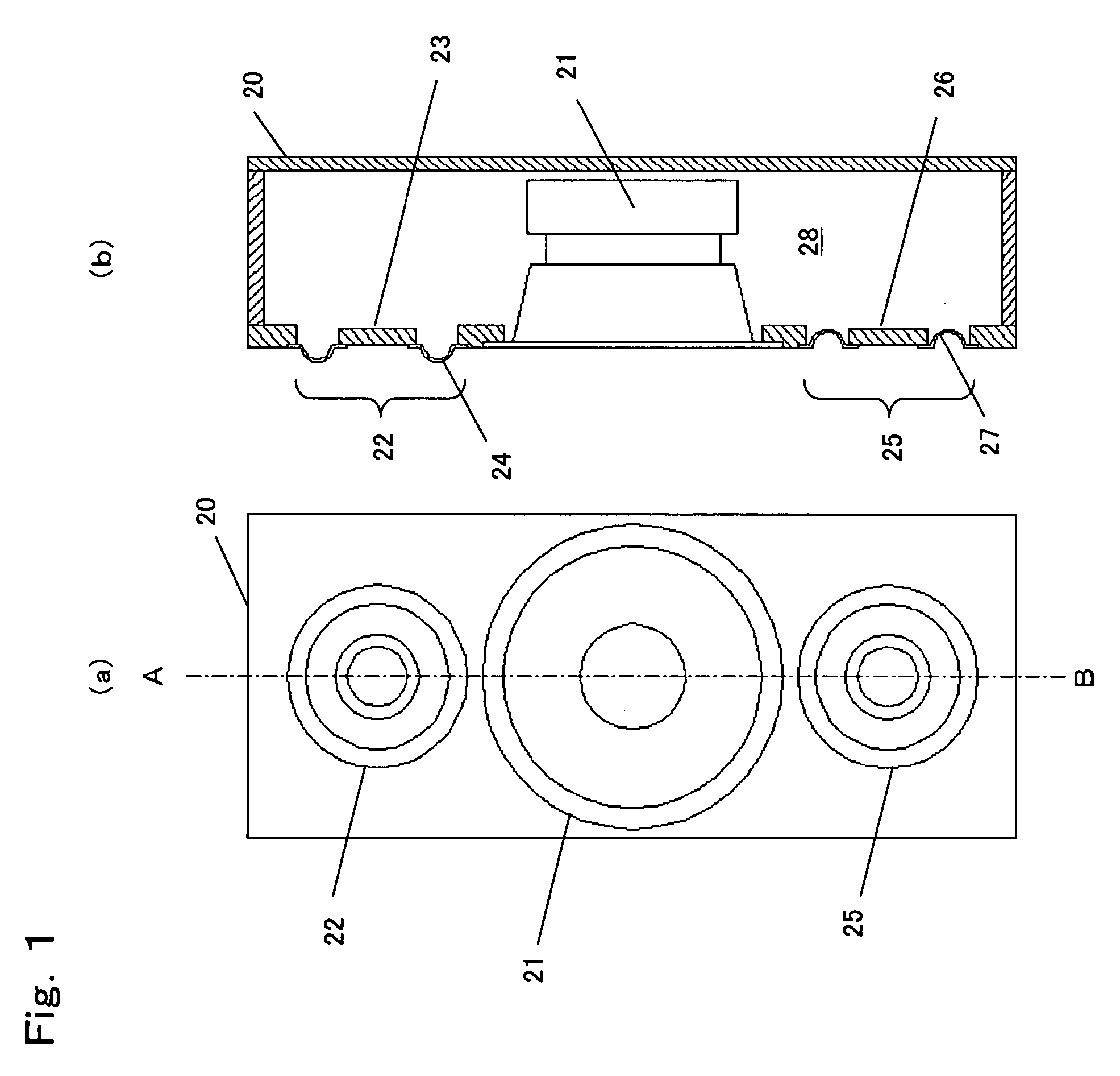
[0095]FIG. 1 illustrates a configuration of a speaker system according to Embodiment 1 of the present invention. Particularly, (a) is a front view of the speaker system, and (b) is a cross-sectional view of the speaker system, taken along line A-B. Also, 20 indicates a cabinet, 21 indicates a speaker unit, 22 indicates a first passive radiator, 23 indicates a diaphragm which is a component of the first passive radiator 22, 24 indicates a roll-shaped convex edge which is a component of the first passive radiator 22, 25 indicates a second passive radiator, 26 indicates a diaphragm which is a component of the second passive radiator 25, 27 indicates a roll-shaped concave edge which is a component of the second passive radiator 25, and 28 indicates a volume of the cabinet 20. Note that the first and second passive radiators 22 and 25 of FIG. 1 are, for example, circular passive radiators.

[0096] An operation of the thus-configured speaker system will be described.

[0097] The operation o...

embodiment 2

[0110]FIG. 5 illustrates a configuration of a speaker system according to Embodiment 2 of the present invention. Particularly, (a) is a front view of the speaker system, and (b) is a cross-sectional view of the speaker system, taken along line C-D. FIG. 6 is an external view of the speaker system. In FIG. 5, components similar to those of FIG. 1 are indicated by the same reference numerals. Embodiment 2 is significantly different from Embodiment 1 in that a sound reflector 30 is provided in front of the first passive radiator 22 and the second passive radiator 25. The reflector 30 is joined with the cabinet 20 so that sounds radiated by the first passive radiator 22 and the second passive radiator 25 are radiated through an opening 31 as indicated by arrows in FIG. 6.

[0111] An operation of the thus-configured speaker system will be described.

[0112] As in Embodiment 1, the vibration of the speaker unit 21 causes the first passive radiator 22 and the second passive radiator 25 to vi...

embodiment 3

[0116]FIG. 7 illustrates a configuration of a speaker system according to Embodiment 3 of the present invention. FIG. 7 is an external view where a portion of the speaker system is cut away. In FIG. 7, 20 indicates a cabinet, 21 indicates a speaker unit attached to a surface of the cabinet 20, 22 indicates a first passive radiator attached to the same surface to which the speaker unit 21 is attached, 24 indicates a convex edge of the first passive radiator 22, 40 indicates a surface of the cabinet 20 perpendicular to the surface to which the first passive radiator 22 is attached, indicates a second passive radiator attached to the surface 40 of the cabinet 20, 27 indicates a concave edge of the second passive radiator 25, 41 indicates a first reflector provided to cover the speaker unit 21 and the first passive radiator 22, 42 indicates an opening formed by the first reflector 41, 43 indicates a second reflector provided to cover the second passive radiator 25, and 44 indicates an o...


PUM


Abstract

A speaker system of the present invention comprises a cabinet, at least one speaker unit attached to the cabinet, and a plurality of passive radiators attached to the cabinet and each including a diaphragm and a supporting system supporting the diaphragm. The speaker system of the present invention is configured so that distortion components of sound pressures radiated from the supporting systems of the plurality of passive radiators are canceled with each other, and sounds radiated by the plurality of passive radiators are radiated in substantially the same direction from the cabinet.

Description

TECHNICAL FIELD [0001] The present invention relates to a speaker system, and more particularly, to a passive radiator speaker system which reduces a distortion in a low-frequency sound range. BACKGROUND ART [0002] In conventional passive radiator speaker systems for reproduction of a low-frequency sound, a single passive radiator is generally used along with a drive speaker unit in a cabinet. However, to reduce a distortion within a low-frequency sound range, a method of using two passive radiators has been proposed (see, for example, see Patent Document 1). [0003]FIG. 21 is a cross-sectional view illustrating a structure of a major portion of a speaker system disclosed in Patent Document 1. In FIG. 21, 1 indicates a cabinet, 2 indicates a drive speaker unit attached inside the cabinet 1, 3 indicates a first passive radiator attached to the cabinet 1, 4 indicates a second passive radiator attached to the cabinet 1, facing the first passive radiator, and 5 indicates an internal spac...

Claims


Application Information

Patent Timeline
IPC IPC(8): H04R25/00H04R1/02H04R9/06
CPCH04R1/2834H04R7/20H04R1/345H04R2499/15H04R2499/13
Inventor SAIKI, SHUJI
Owner SOVEREIGN PEAK VENTURES LLC
Why Eureka
Try Eureka