Method for estimating self-vibration of milling tool in the operating process

a technology of self-vibration and milling tool, which is applied in the direction of adaptive control, process and machine control, instruments, etc., can solve the problems of generating noise or vibration of processing machines, reducing the number of correction steps, and reducing the relative vibration of tools and work

Inactive Publication Date: 2007-08-30
HITACHI LTD
View PDF8 Cites 16 Cited by
  • Summary
  • Abstract
  • Description
  • Claims
  • Application Information

AI Technical Summary

Benefits of technology

[0020] As a result, even in a case where the rotation shaft of the tool is not perpendicular to the feeding direction during processing of a wing surface of a fluid machine component o

Problems solved by technology

In a cutting step by a rotary tool, relative vibrations of the tool and a work are sometimes generated due to low stiffness on a tool side or a work side or the like.
When the vibration (an amplitude) is large, a noise or a vibration of a processing machine

Method used


Image

  • Method for estimating self-vibration of milling tool in the operating process
  • Method for estimating self-vibration of milling tool in the operating process
  • Method for estimating self-vibration of milling tool in the operating process

Examples


Embodiment Construction

[0031] A method for estimating a self-excited cutting vibration during oblique cutting according to the present invention will hereinafter be described with reference to the drawings.

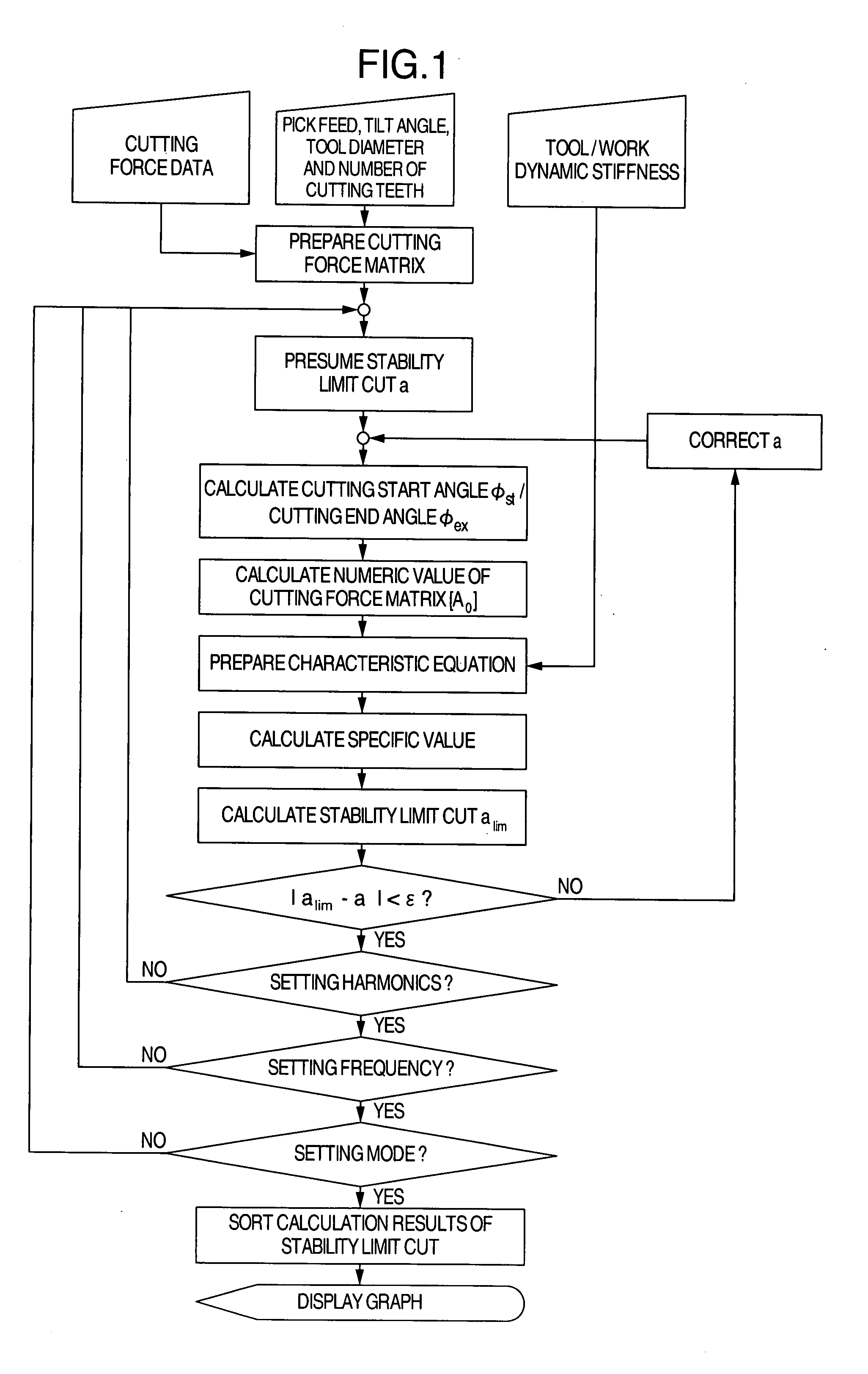
[0032] First, in the method according to the present invention, as shown in a flow chart of FIG. 1, the followings are given as input values:

[0033] (1) a cutting force coefficient determined by a combination of a tool geometry of a cutting tool and a material of a work;

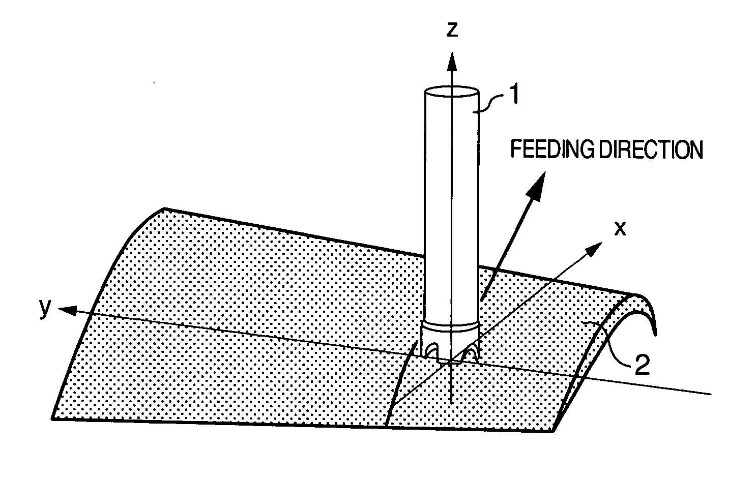
[0034] (2) a pick feed amount Pf, a work oblique angle γ, a tool diameter R and the number N of cutting teeth; and

[0035] (3) dynamic stiffness of the tool and the work.

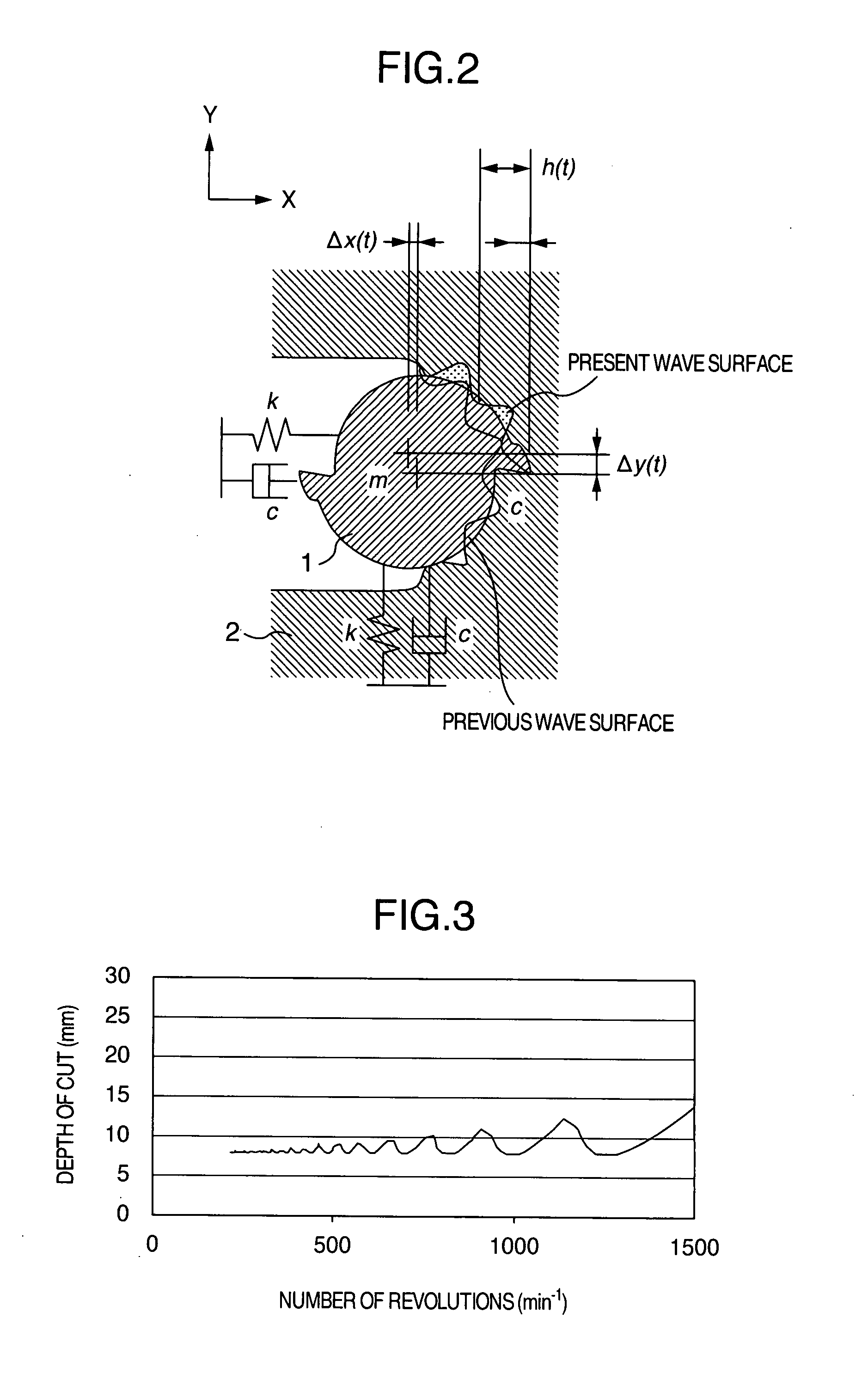
[0036] As described in the above document, in FIG. 2, a fluctuation amount h(φj) of a chip thickness at a time when a j-th cutting tooth is disposed at an angle φj from a direction (a Y-direction) perpendicular to a feeding direction, that is, an X-direction, is given by Equation (5):

h(φj)=(Δx cos φj+Δy sin φj)(φj)  (5)

in which Δx, Δy are displacement amounts of the c...


PUM

PropertyMeasurementUnit
Depthaaaaaaaaaa
Stabilityaaaaaaaaaa

Abstract

In a cutting method of an oblique surface by a rotary tool, for analyzing in advance a stability limit depth of cut with respect to a self-excited cutting vibration in consideration of a pick feed amount and a work oblique angle and reducing the number of steps necessary for preparation and correction of NC data, a tool diameter, the number of cutting teeth and dynamic stiffness of the rotary tool, a cutting force coefficient determined by a combination of the tool and work materials, dynamic stiffness of the work, the pick feed amount, oblique angles between the tool and the work and the like are used as input values, an initial value of the stability limit depth of cut is determined based on the input values, and calculation is performed based on the initial value. In this case, the initial value is compared with the calculated value, the initial value is corrected by a certain rule, and the calculation is repeated until both the initial value and the calculated value fall in a constant error range to thereby calculate the stability limit depth of cut during the oblique cutting.

Description

INCORPORATION BY REFERENCE [0001] The present application claims priority from Japanese application JP 2005-365694 filed on Dec. 20, 2005, the content of which is hereby incorporated by reference into this application. BACKGROUND OF THE INVENTION [0002] The present invention relates to a method for estimating stable processing conditions in advance in order to prevent a self-excited cutting vibration which causes deterioration of a processing precision and breakage of a cutting tool in a case of processing a three-dimensional shape by a machine tool in which the cutting tool is moved while rotating the cutting tool. [0003] In a cutting step by a rotary tool, relative vibrations of the tool and a work are sometimes generated due to low stiffness on a tool side or a work side or the like. The relative vibrations of the tool and the work are generated by a forced vibration or a self-excited vibration. [0004] In the relative vibrations due to the former forced vibration, when a cutting ...

Claims


Application Information

Patent Timeline
IPC IPC(8): B26D1/12
CPCB23C3/00B23C2220/48Y10T82/10Y10T409/307224Y10T407/19
Inventor ONOZUKA, HIDEAKIKYOI, MASAYUKI
Owner HITACHI LTD
Why Eureka
Try Eureka