Sealed prismatic battery

a prismatic battery and seal technology, applied in the direction of cell components, flat cell grouping, sustainable manufacturing/processing, etc., can solve the problems of large component resistance, major barrier to the realization of higher power output or battery life improvement, and high cost, and achieve lower internal resistance per cell, the effect of increasing power

Inactive Publication Date: 2007-08-30
PANASONIC CORP +1
View PDF3 Cites 37 Cited by
  • Summary
  • Abstract
  • Description
  • Claims
  • Application Information

AI Technical Summary

Benefits of technology

[0011] The present invention has been devised in light of the problems in prior art described above, its object being to provide a sealed prismatic battery having lower internal resistance per cell and being capable of outputting higher power by ensuring that power generation of all the electrode plate groups is uniform.
[0016] With this structure, not only is the distance between each electrode plate and collectors short but also the distance between the collectors and conductive plates are short because they are connected together at one or more than one location in the middle part of the collectors, whereby resistance between the electrode plates and conductive plates is small. The disadvantage of longer current flow paths can be counterbalanced by employing a material that has lower resistance for the conductive plates, so the conductive plates can be connected to external terminals at any given location while resistance is maintained low. These all lead to lower internal resistance per cell of the battery.

Problems solved by technology

The cells are connected via a long connection path with many connection parts in this battery, resulting in large components' resistance.
In fact, the proportion of the components' resistance in such a battery to reaction resistance caused by the reaction between positive and negative electrode plates and liquid electrolyte in the battery was as high as 40 to 50%, and the high heat generation because of the large internal resistance was a major barrier to the realization of higher power output or improvement in battery life.
There was also the problem of high costs because of the large number of components required for the complex connection structure of the cells.
As a result, the electrode plate groups 108 cannot exhibit their power generating properties uniformly, causing considerable power loss.

Method used


Image

  • Sealed prismatic battery
  • Sealed prismatic battery
  • Sealed prismatic battery

Examples


Embodiment Construction

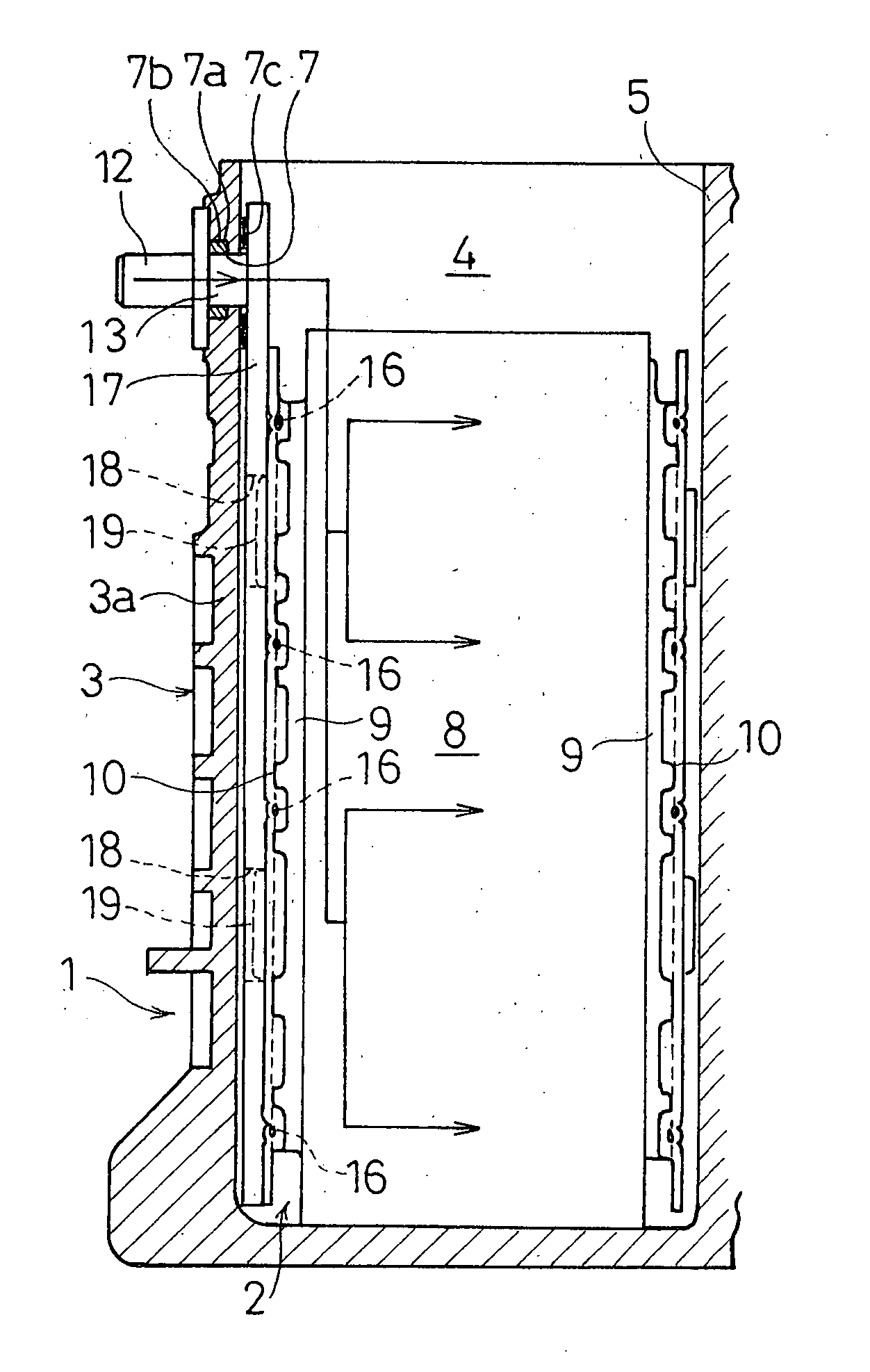
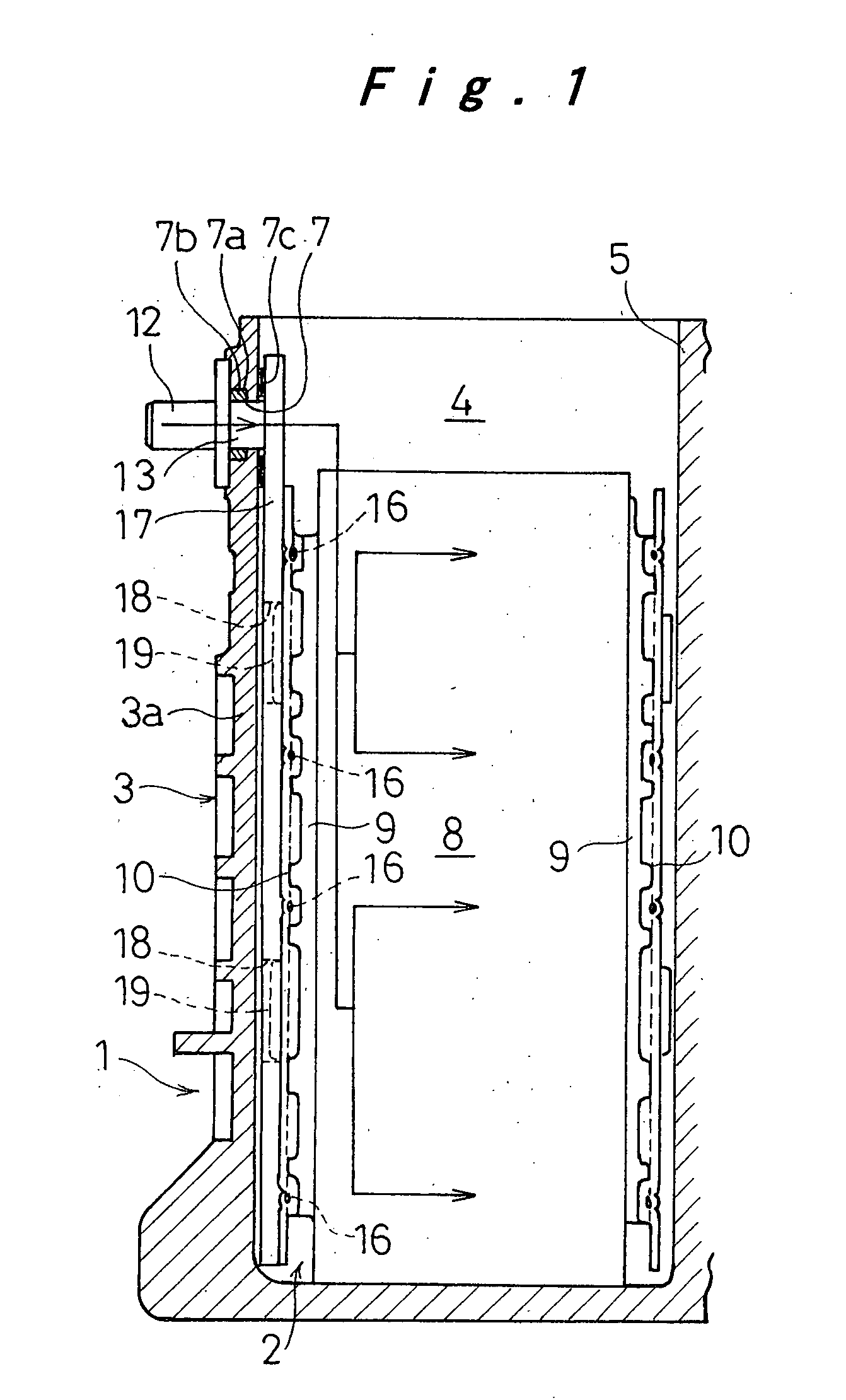
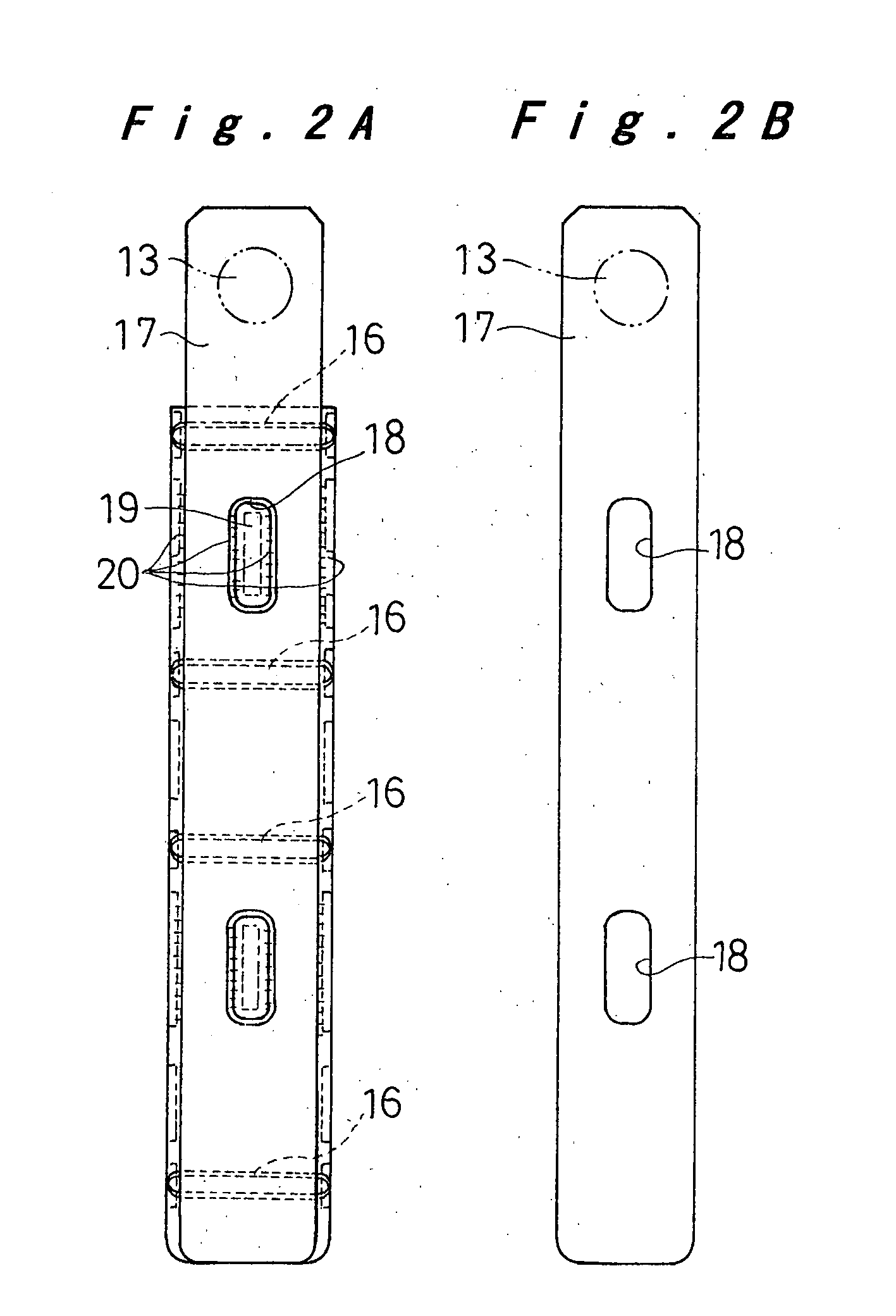
[0024] One embodiment of a sealed prismatic battery according to the present invention will be hereinafter described with reference to FIG. 1 to FIG. 2B.

[0025] The battery 1 has a prismatic battery case 3 made of a plurality of prismatic cell cases 4, which have short lateral walls and long lateral walls and are connected together in such a manner that their short lateral walls are used as partition walls 5. The battery case 3 is made of synthetic resin such as a PP / PPE alloy which is repellent against liquid electrolyte. In an upper part of the end walls 3a of the battery case 3 are formed connection holes 7, in which connection bosses 13 of connection terminals 12 will be fitted. The connection holes 7 are provided with grooves 7a at their inner periphery for accommodating a sealing material 7b such as an O-ring.

[0026] Each cell case 4 constitutes a cell 2, accommodating liquid electrolyte and an electrode plate group 8, to both sides of which collectors 10 have been bonded. The...


PUM

PropertyMeasurementUnit
resistanceaaaaaaaaaa
conductiveaaaaaaaaaa
lengthaaaaaaaaaa

Abstract

A sealed prismatic battery has a battery case made of a plurality of prismatic cell cases coupled together via partition walls. Electrode plate groups are accommodated together with liquid electrolyte in each of the cell cases. Each electrode plate group consists of alternately stacked-up positive and negative electrode plates with separators interposed therebetween, lead portions of positive and negative electrode plates being protruded on opposite sides. Collectors are bonded to these lead portions. Between the collectors and end walls (and / or partition walls) of the battery case are provided conductive plates that are connected to the collectors one or more than one location in their middle part so as to decrease the resistance between connection terminals and the electrode plate groups.

Description

[0001] The present disclosure relates to subject matter contained in priority Japanese Patent Application No. 2002-14704, filed on Jan. 23, 2002, the contents of which is herein expressly incorporated by reference in its entirety. BACKGROUND OF THE INVENTION [0002] 1. Field of the Invention [0003] The present invention relates to a sealed prismatic battery, and particularly to a prismatic rechargeable battery module consisting of a plurality of cells with lower internal resistance. [0004] 2. Description of Related Art [0005] One known rechargeable battery module consisting of a plurality of cells to achieve required power capacity has the following structure: The plurality of prismatic cells are arranged in parallel, with their longer lateral walls in contact with each other, and united by restraining bands together with end plates placed on the outer sides of the cells at the either end. Leads extending from the top ends of electrode plates of the cells upwards are connected to ter...

Claims


Application Information

Patent Timeline
Patent Type & Authority Applications(United States)
IPC IPC(8): H01M2/24H01M2/20H01M2/02H01M50/528H01M10/04H01M10/28H01M50/529H01M50/533H01M50/534H01M50/536H01M50/54
CPCH01M2/24H01M10/0413H01M2/266Y02E60/10H01M50/529H01M50/54Y02P70/50H01M50/536H01M50/533H01M50/534
Inventor ASAHINA, TAKASHIKAJIYA, HIROMIHAMADA, SHINJIETO, TOYOHIKO
Owner PANASONIC CORP
Why Eureka
Try Eureka