Multi-bath apparatus and method for cooling superconductors

a superconductors and multi-bath technology, applied in the field of superconductors, can solve the problems of difficult maintenance, less than quick and efficient restoration of superconducting state, and sudden increase in impedance of superconducting fcl

Inactive Publication Date: 2007-09-06
BOC GRP INC
View PDF12 Cites 16 Cited by
  • Summary
  • Abstract
  • Description
  • Claims
  • Application Information

AI Technical Summary

Benefits of technology

[0009] A multi-bath apparatus and method for cooling a superconductor includes a cooling bath comprising a first cryogen, the cooling bath surrounding a superconducting device and maintained at a first pressure, and a shield bath comprising a second cryogen, the shield bath surrounding the cooling bath and maintained at a second pressure, wherein the cooling bath and the shield bath are in a thermal relationship with one another and the first pressure generally exceeds the second pressure. Preferably, the first cryogen is subcooled, the second cryogen is saturated, the cryogens are, for example, liquid nitrogen, and the superconducting device is, for example, a high temperature superconducting device, such as a fault current limiter. Following a thermal disruption to the superconducting device, the first pressure is restored to the cooling bath and the second pressure is restored to the shield bath.

Problems solved by technology

However, if a fault current occurs, then the superconducting FCL suddenly provides increased impedance.
However, once the superconducting FCL experiences a quench due to a fault current event or events, restoring the superconducting state has proven to be less than quick and efficient.
In addition, the advantages of using pressurized, subcooled, liquid nitrogen have been difficult to maintain following a fault current event that disrupts the uniformity of the subcooling.

Method used


Image

  • Multi-bath apparatus and method for cooling superconductors
  • Multi-bath apparatus and method for cooling superconductors
  • Multi-bath apparatus and method for cooling superconductors

Examples


Embodiment Construction

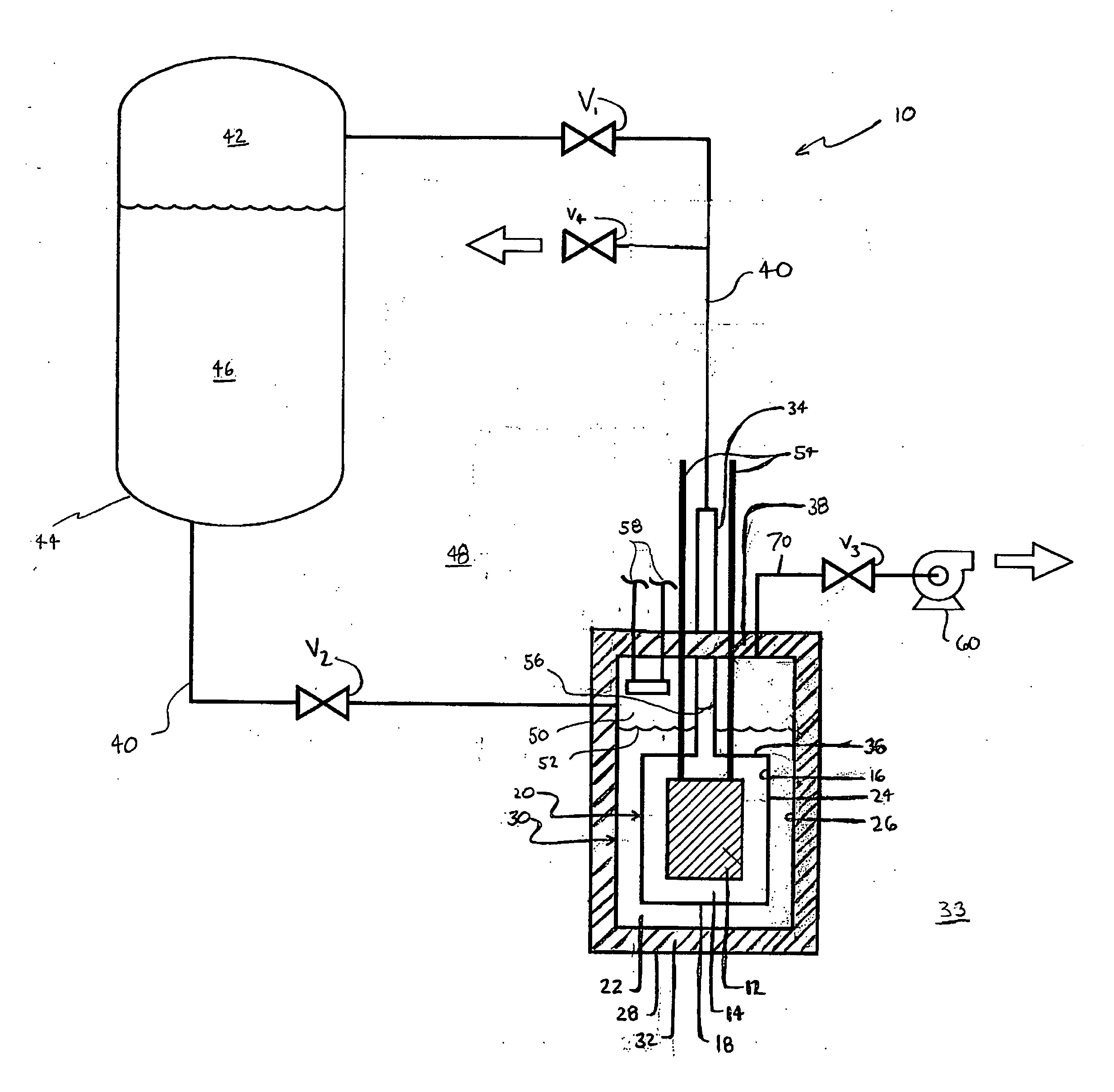
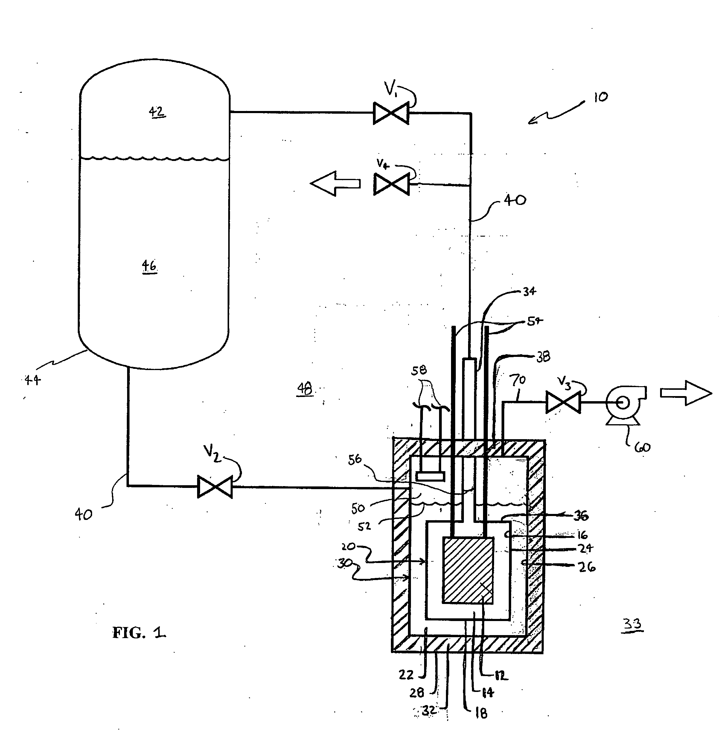
[0013] Referring now to FIG. 1, cryogenic system 10 is depicted in which the inventive arrangements are practiced according to a first preferred embodiment. More specifically, FIG. 1 is schematic view of cryogenic system 10 comprising its most basic elements, including superconducting device 12, such as a fault current limiter, transformer, motor, generator, or the like.

[0014] Superconducting device 12 is surrounded by, and immersed in, at least partially, and preferably wholly, first cryogen 14 contained within internal walls 16 of inner vessel 18 to define cooling or inner bath 20. In like fashion, inner vessel 18 is surrounded by, and immersed in, at least partially, and preferably wholly, second cryogen 22 contained by and between external walls 24 of inner vessel 18 and internal walls 26 of cryostat 28 to define shield or outer bath 30. As will be elaborated upon, cooling bath 20 and shield bath 30 are in thermal contact (i.e., a heat exchange relationship) with one another, b...


PUM


Abstract

A multi-bath apparatus and method for cooling a superconductor includes both a cooling bath comprising a first cryogen and a shield bath comprising a second cryogen. The cooling bath surrounds the superconductor, and the shield bath surrounds the cooling bath. The cooling bath is maintained at a first pressure and subcooled, while the shield bath is maintained at a second pressure and saturated. The cooling bath and the shield bath are in a thermal relationship with one another, and the first pressure is greater the second pressure. Preferably, the cryogens are liquid nitrogen, and the superconductor is a high temperature superconductor, such as a current limiter. Following a thermal disruption to the superconductor, the first pressure is restored to the cooling bath and the second pressure is restored to the shield bath in order to restore the superconductor to a superconductive state.

Description

BACKGROUND OF THE INVENTION [0001] In general, the invention relates to superconductors, and, more specifically, to a multi-bath apparatus and method for cooling superconductors. DESCRIPTION OF RELATED ART [0002] High Temperature Superconducting (HTS) devices can operate over a wide temperature range, but usually operate best at temperatures below their critical transition temperature. For many HTS devices, these preferred operating temperatures are below the normal boiling point of liquid nitrogen (77.4 K). [0003] Superconductors are commonly recognized as ideal current limiters because of an inherent contrast in their electrical conducting capacity between their superconducting and non-superconducting states. Fault Current Limiters (FCLs) are well-known devices that reduce large fault currents to lower levels that can be safely handled by traditional equipment such as circuit breakers. Typically and ideally, an FCL operates in the background of an overall system, e.g., an electric...

Claims


Application Information

Patent Timeline
Patent Type & Authority Applications(United States)
IPC IPC(8): F25B19/00F25D23/12
CPCF25B2500/06H01F6/04F25D19/00F25D3/10Y10S505/899F25B19/00F25D23/12
Inventor LEE, RON
Owner BOC GRP INC
Why Eureka
Try Eureka