Q-damping of a high temperature superconductor self-resonant coil in a nuclear quadropole detection system

Inactive Publication Date: 2005-06-30
EI DU PONT DE NEMOURS & CO
View PDF84 Cites 26 Cited by
  • Summary
  • Abstract
  • Description
  • Claims
  • Application Information

AI Technical Summary

Benefits of technology

[0029] The advantageous effects of this invention are demonstrated by a series of examples, as described below. The embodimen

Problems solved by technology

Problems associated with such a detector using conventional systems are the decrease in detectabili

Method used


Image

  • Q-damping of a high temperature superconductor self-resonant coil in a nuclear quadropole detection system
  • Q-damping of a high temperature superconductor self-resonant coil in a nuclear quadropole detection system
  • Q-damping of a high temperature superconductor self-resonant coil in a nuclear quadropole detection system

Examples


example 1

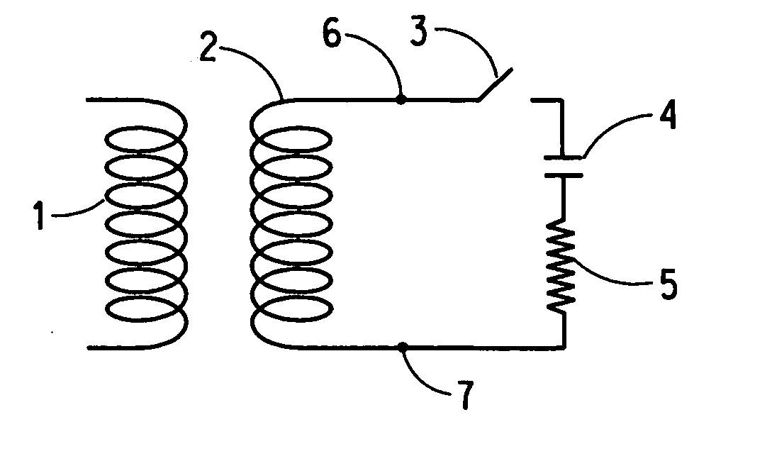
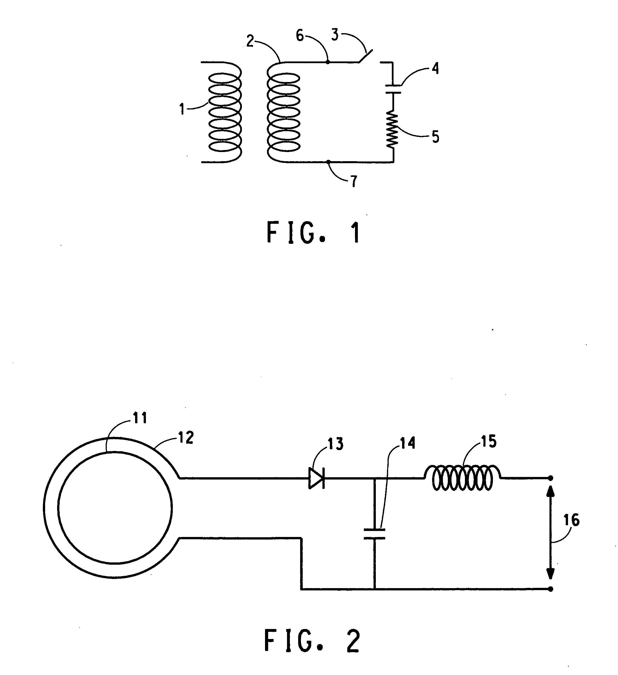
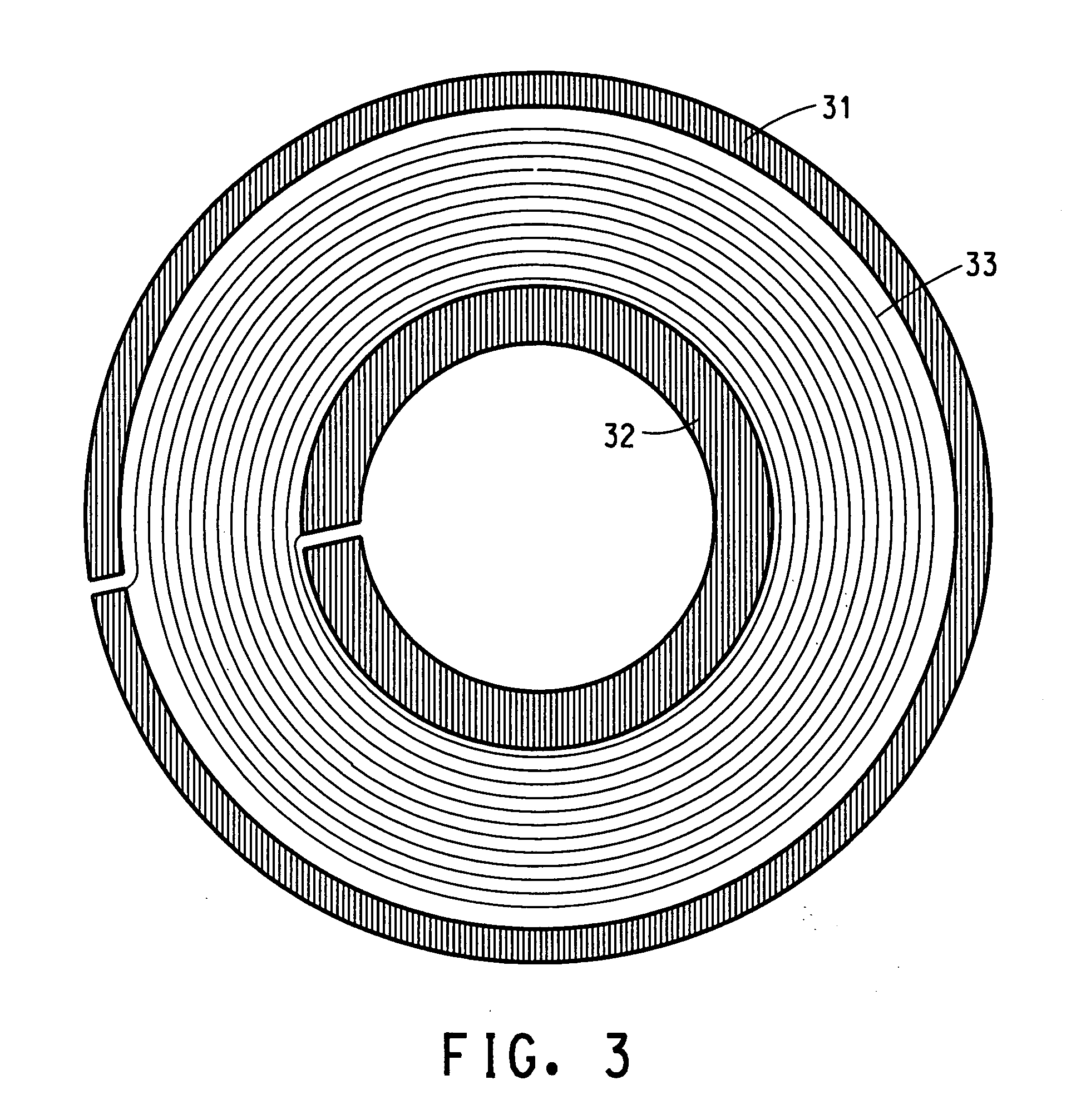
[0030] The purpose of this example is to demonstrate the rapid recovery time achieved with the Q-damping circuit and the diode operated at a forward bias such that the diode is resistive. The Q-damping circuit used is shown in FIG. 2. The HTS self-resonant transmit and receive coil used is comprised of two coupled essentially identical Tl2Ba2CaCu2O8 planar coils. Each of the coupled coils is on a sapphire (Al2O3) substrate with the coil design configuration shown in FIG. 3 on both sides of the substrate.

[0031] A clean, polished single crystal sapphire substrate with a diameter of 2 inches (5.1 cm) and an approximate thickness of 0.018 inches (0.46 mm) was obtained from Union Carbide Corp. An epitaxial CeO2 buffer layer is grown on both sides of the substrate by off-axis sputter deposition with the substrate temperature held in the range of about 700-800° C. Off-axis magnetron sputtering of a Ba:Ca:Cu oxide target is used to deposit, at room temperature (about 20° C.), an amorphous ...

example 2

[0041] The purpose of this example is to demonstrate the detection of NQR signals from sodium nitrate using the Q-damping circuit of the instant invention. The same HTS self-resonant transmit and receive coil, comprised of the same two coupled essentially identical Tl2Ba2CaCu2O8 planar coils and the copper single loop coupling the HTS self-resonant transmit and receive coil to the Q-damping circuit, used in Example 1 is used in Example 2. The Q-damping circuit is identical to that used in Example 1 except that the inductor 15 had inductance of 3300 μH. In addition, a 0.1 μH ceramic capacitor is added to the circuit between the bias voltage VC electrode attached to the inductor 15 and ground for additional noise suppression.

[0042] The sodium nitrate sample is placed approximately 1 cm from the HTS self-resonant transmit and receive coil. A bias voltage VC is set at +8 V, a reverse bias for the diode, to inactivate the Q-damping circuit, and a bias voltage is set at −0.6 V, a forward...


PUM


Abstract

The use of a bias controlled diode in the Q-damping circuit of a high temperature superconductor transmit, receive, or transmit and receive self-resonant coil in a nuclear quadrupole resonance detection system results in improved performance. The diode is operated with a forward bias such that the diode is resistive with a resistance of about 10 to about 1000 ohms.

Description

[0001] This application claims the benefit of U.S. Provisional Application No. 60 / 524,472, filed on Nov. 24, 2003, which is incorporated in its entirety as a part hereof for all purposes.FIELD OF THE INVENTION [0002] This invention relates to a nuclear quadrupole resonance detection system, and the use of a bias controlled diode in a Q-damping circuit for a high temperature superconductor transmit, receive, or transmit and receive, self-resonant coil. BACKGROUND OF THE INVENTION [0003] The use of nuclear quadrupole resonance (NQR) as a means of detecting explosives and other contraband has been recognized for some time—see e.g. T. Hirshfield et al, J. Molec. Struct. 58, 63 (1980); A. N. Garroway et al, Proc. SPIE 2092, 318 (1993); and A. N Garroway et al, IEEE Trans. on Geoscience and Remote Sensing, 39, pp. 1108-1118 (2001). NQR provides some distinct advantages over other detection methods. NQR requires no external magnet such as required by nuclear magnetic resonance. NQR is sens...

Claims


Application Information

Patent Timeline
IPC IPC(8): G01R33/44G01V3/14
CPCH04N5/44513G01V3/14H04N21/47
Inventor ALVAREZ, ROBBY L.
Owner EI DU PONT DE NEMOURS & CO
Why Eureka
Try Eureka