
Pneumatic Tire

a technology of pneumatic tires and tires, applied in the field of pneumatic tires, can solve the problems of insufficient wear resistance of conventional tires, inability to meet the requirements, and decrease the wear resistance, so as to improve the wear resistance, improve the drivability, and suppress the uneven wear

Inactive Publication Date: 2007-09-06
BRIDGESTONE CORP
View PDF5 Cites 10 Cited by
  • Summary
  • Abstract
  • Description
  • Claims
  • Application Information

AI Technical Summary

Benefits of technology

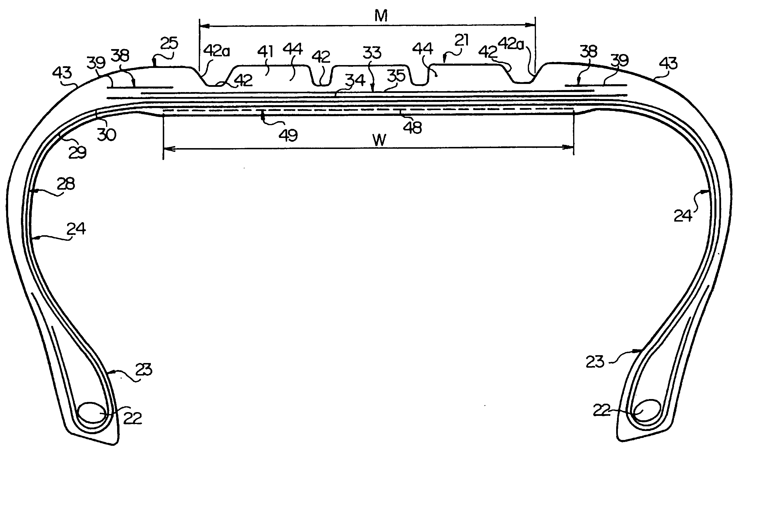
[0006] Thus, the present inventor has repeatedly studied and found that a ground-contact pressure of the land portions located between the tread end and the main groove and between the adjacent main grooves in the ground contact area is high at both transversely end parts near the main groove while it is low at the transversely center part, which means uneven pressure distribution, so that the drivability is lowered and uneven wear may caused to decrease the wear resistance since the both transversely end parts of the land portion wear in an earlier stage with respect to the center part.
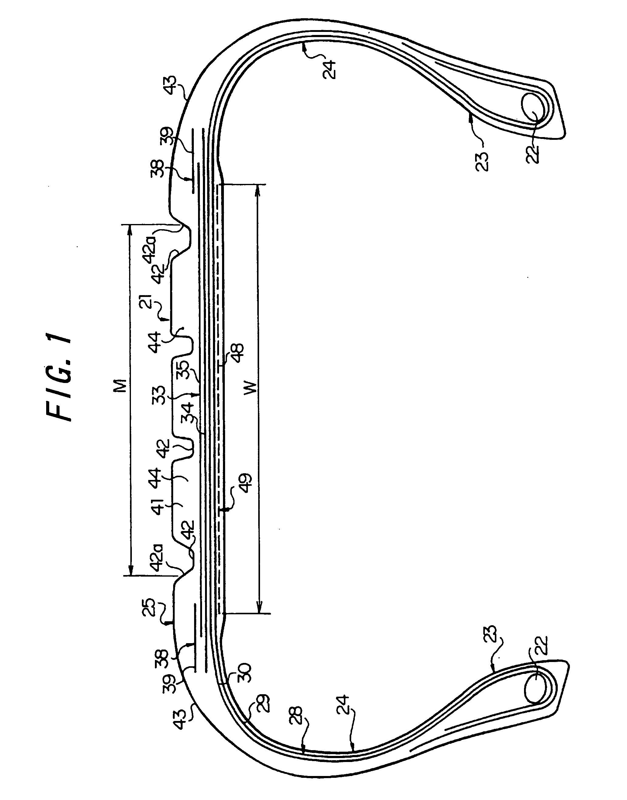
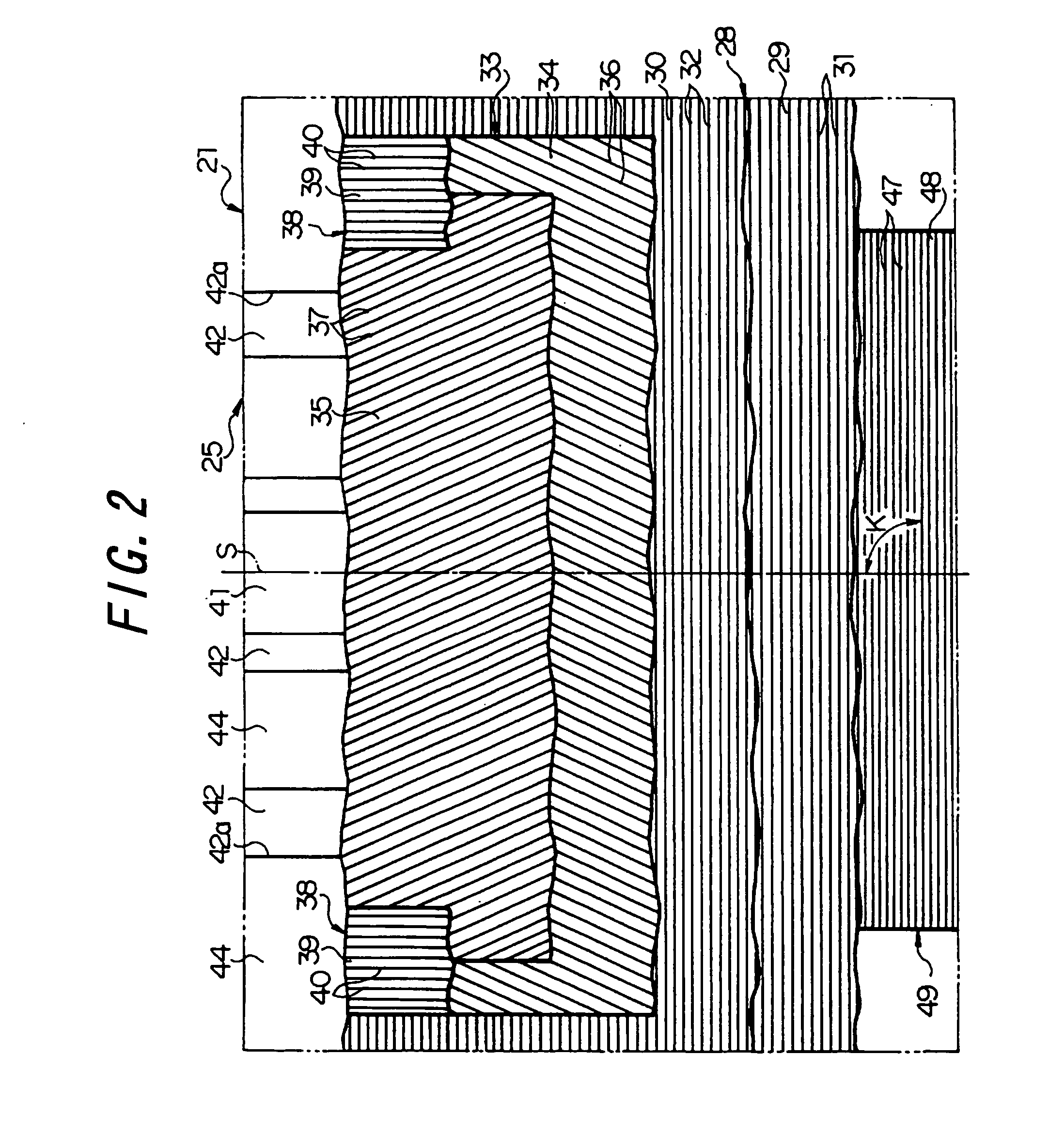
[0012] In the present invention, the reinforcing layer is arranged at the position spaced from the neutral axis of deformation in the compressed side in a certain distance, i.e. radially inside of the radially outermost carcass ply, and the carcass cords which extend in the direction including the tire width direction and its approximate direction and which act as supports for resisting against the compression force are embedded in the reinforcing layer. As a result, the above-mentioned curved deformation can be effectively suppressed, thereby obtaining a uniform distribution of the ground contact pressure in the land part to improve the drivability as well as suppressing the uneven wear to improve the wear resistance.
[0013] With the tire configured according to claim 2, the above-mentioned curved deformation is strongly suppressed, thereby remarkably improving the drivability and wear resistance. Moreover, with the tire configured according to claim 3, the radial distance from the neutral axis of deformation to the reinforcing layer becomes longer to be able to further enhance the supporting function of the reinforcing layer.
[0014] With the tire configured according to claim 4, the cut edge of the steel cord in the reinforcing layer is surrounded by the carcass plies, so that it can effectively prevent cracks from occurring at the outer edge of the reinforcing layer in the width direction. Furthermore, with the tire configured according to claim 5, an operation of building the tire, i.e. an operation of attaching the reinforcing layer can be simplified and the curved deformations at all main grooves can be effectively suppressed.
[0015] When the extending direction of the steel cords in the reinforcing layer is made parallel with the extending direction of the reinforcing cord in the carcass ply adjacent to the reinforcing layer, the occurrence of the cracks at the outer edge in the width direction of the reinforcing layer, i.e. the cut edge of the steel cord can be more effectively prevented as compared with the case where these extending directions intersect with each other.

Problems solved by technology

The above-mentioned types of conventional tires, however, cannot sufficiently fulfill the requirement.
Thus, the present inventor has repeatedly studied and found that a ground-contact pressure of the land portions located between the tread end and the main groove and between the adjacent main grooves in the ground contact area is high at both transversely end parts near the main groove while it is low at the transversely center part, which means uneven pressure distribution, so that the drivability is lowered and uneven wear may caused to decrease the wear resistance since the both transversely end parts of the land portion wear in an earlier stage with respect to the center part.

Method used


Image

  • Pneumatic Tire
  • Pneumatic Tire
  • Pneumatic Tire

Examples


examples

[0044] Next, the experimental example 1 is discussed. For this experiment, there are prepared a conventional tire 1 in which no reinforcing layer is arranged, a comparative tire 1 in which steel cords having the cross angle K of 30 degrees are embedded in a reinforcing layer and the reinforcing layer is arranged radially inside of the innermost carcass ply, an example tire 1 in which steel cord having the cross angle K of 90 degrees are embedded in a reinforcing layer and the reinforcing layer is arranged between two carcass plies, an example tire 2 in which steel cord having the cross angle K of 90 degrees are embedded in a reinforcing layer and the reinforcing layer is arranged radially inside of the innermost carcass ply, and an example tire 3 in which steel cord having the cross angle K of 70 degrees are embedded in a reinforcing layer and the reinforcing layer is arranged radially inside of the innermost carcass ply.

[0045] The above-mentioned tires are for passenger vehicle an...


PUM


Abstract

The ground contact pressure on land portions 44 is uniformed so that drivability is improved and uneven wear is suppressed to improve wear resistance. The parts of the carcass layer 28 and belt layer 33 overlapping with the main grooves 42 are convexly curved toward the outside in the radial direction due to the internal pressure. The reinforcing layer 49 is arranged at the position spaced from the neutral axis of deformation in the compressed side in a certain distance, i.e. radially inside of the radially outermost carcass ply 30, and the steel cords 47 which extend in the direction including the tire width direction and its approximate direction and which act as supports for resisting against the compression force are embedded in the reinforcing layer. As a result, the above-mentioned curved deformation can be effectively suppressed.

Description

TECHNICAL FIELD [0001] The present invention relates to a pneumatic tire having a reinforcing layer arranged in a tread portion to overlap with a carcass layer. RELATED ART [0002] A pneumatic tire such as described in Japanese Patent Application Laid-open No. 205,509 / 2002 is known as a prior art tire. [0003] Such a tire has a carcass layer which toroidally extends between beads and which is composed of two carcass plies, a belt layer which is disposed radially outside of the carcass layer and which is composed of plural belt plies, and a tread which is disposed radially outside of the belt layer and which is provided with plural main grooves on the outer circumference. Embedded in the two carcass plies are reinforcing cords of organic fiber inclining in opposite directions with respect to the tire equator, while embedded in the belt plies are non-stretchable reinforcing cords such as a steel cord or reinforcing cord of organic fiber inclining in opposed directions at 10 to 40 degree...

Claims


Application Information

Patent Timeline
Patent Type & Authority Applications(United States)
IPC IPC(8): B60C9/00B60C9/18B60C9/08B60C9/20B60C9/22
CPCB60C9/2009B60C9/22Y10T152/10801Y10T152/10792Y10T152/10765Y10T152/10855B60C2009/1892
Inventor ISHIYAMA, MAKOTO
Owner BRIDGESTONE CORP
Learn More