Optical system for barcode scanner

a barcode scanner and optical system technology, applied in the field of barcode scanners, can solve the problems of reducing the yield rate after installation, reducing the cost of manufacturing the barcode scanner, and reducing the yield ra

Inactive Publication Date: 2007-09-06
RIOTEC
View PDF3 Cites 40 Cited by
  • Summary
  • Abstract
  • Description
  • Claims
  • Application Information

AI Technical Summary

Problems solved by technology

de signal. However, because this design uses two laser diode modules A1 and two standing cylindrical lenses A2 to provide two projection light beams, the manufacturing cost of the barcode scann
be obtained. However, this limitation complicates the installation, and the yield rate after install
lenses design. However, this design encounters th
Therefore, this design shortens the distance in X-axis, however it requires a relatively greater space in Z-axis.
However, the area of the reservation region C2 is small and is not enough to design illumination.
Therefore, the light source structure is designed sideways from reservation region C2, thereby increasing the designed space and cost.

Method used


Image

  • Optical system for barcode scanner
  • Optical system for barcode scanner
  • Optical system for barcode scanner

Examples


Embodiment Construction

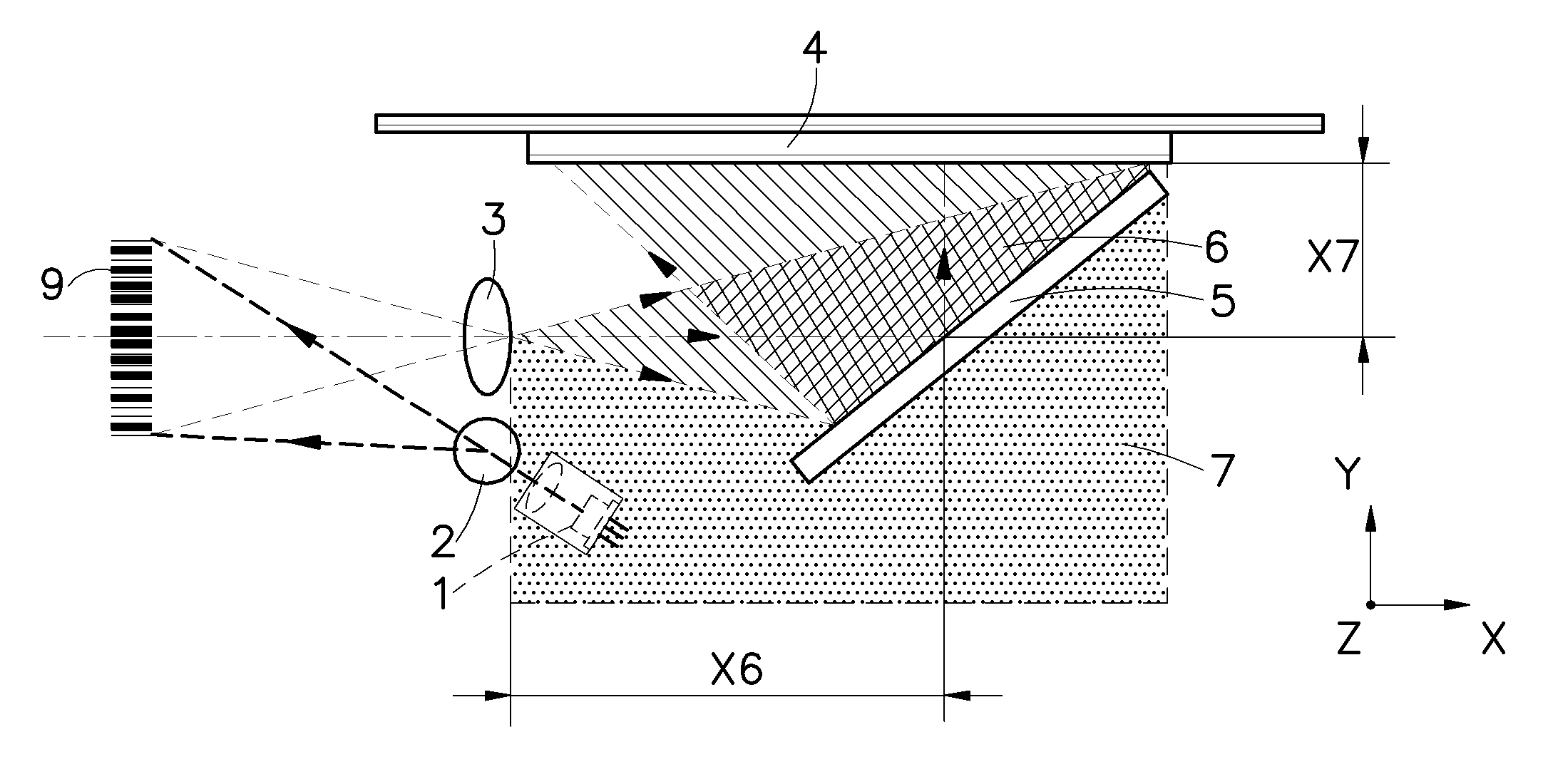
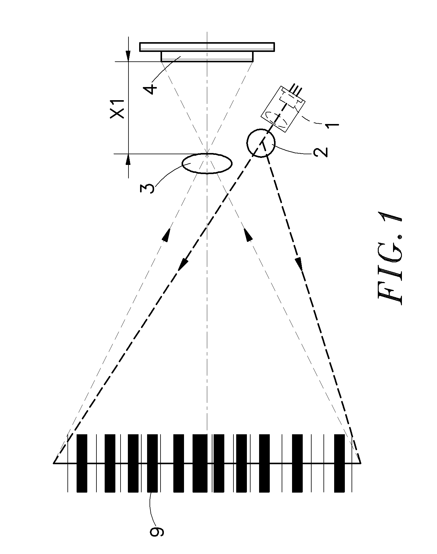
[0024]Referring to FIG. 1, an optical system in accordance with a first embodiment of the present invention is shown comprised of a light source 1, a standing cylindrical lens 2, a focusing lens 3, and a linear sensor array 4.

[0025]The light source 1 can be formed of a light emitting element and a collimator to provide a dot-shaped light beam of parallel light in a slanting angle relative to a plane of a barcode 9 of a product to be scanned.

[0026]The standing cylindrical lens 2 is adapted to expand the dot-shaped light beam produced by the light source 1 as a line-shaped light beam to project onto the barcode 9 of the product.

[0027]The focusing lens 3 is adapted to receive the barcode image reflected by the barcode 9 and to focus the barcode image. Further, the focal distance of the focusing lens 3 is X1.

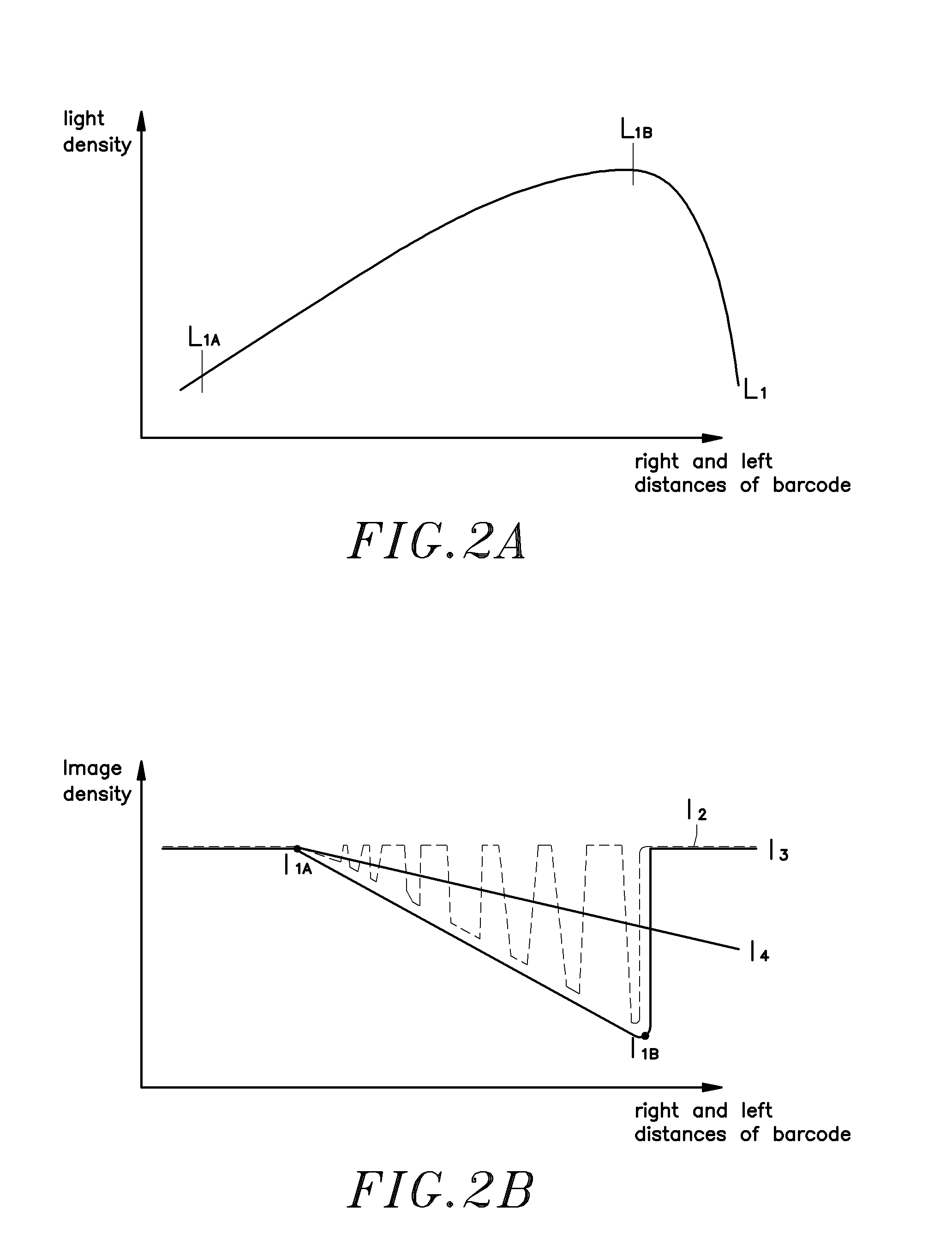
[0028]The linear sensor array 4 is adapted to receive the image focused by the focusing lens 3, which image has different levels between the left side and the right side.

[0029]Refer...


PUM


Abstract

An optical system used in a barcode scanner is disclosed to include a light source for emitting a dot-shaped light beam in a slanting angle, a standing cylindrical lens for expanding the dot-shaped light beam produced by the light source as a line-shaped light beam onto a barcode of a product in a slanting angle, which line-shaped light beam showing a light intensity distribution curve that is asymmetric between the left side and the right side, a linear sensor array, and a focusing lens for focusing a reflective image of the barcode onto the linear sensor array. A reflector means can be provided for overlapping the light path to reduce the size of the barcode scanner. Further, a shaking means may be used to cause reciprocation of the light beam in direction perpendicular to the light path of the light source, thereby eliminating image noises due to existence of black holes.

Description

[0001]This application claims the priority benefit of Taiwan patent application number 095203387 filed on Mar. 1, 2006.BACKGROUND OF THE INVENTION[0002]1. Field of the Invention[0003]The present invention relates to a barcode scanner and more particularly, to an optical system for barcode scanner, which uses a standing cylindrical lens to expand a dot-shaped light beam emitted by the light source as a line-shaped light beam such that the light intensity curve of the line-shaped light beam that falls to a barcode shows an asymmetric characteristics between the left side and the right side. The optical system lowers the manufacturing cost of the barcode scanner and reduces the size of the barcode scanner by means of overlap of light paths, and eliminates image noises due to the black holes in the light beam by means of the application of shaker means.[0004]2. Description of the Related Art[0005]Conventional barcode scanners commonly use a linear sensor array to receive reflective imag...

Claims


Application Information

Patent Timeline
Patent Type & Authority Applications(United States)
IPC IPC(8): G06K7/10G06K15/12
CPCG06K7/10702G06K7/10831G06K7/10732
Inventor TIEN, KAI-YUAN
Owner RIOTEC
Why Eureka
Try Eureka