
Optically Guided Munition

a technology of guided munitions and mortar shells, applied in direction controllers, instruments, weapons, etc., can solve problems such as using non-uniform pixels, and achieve the effects of improving accuracy, low cost, and increasing caliber

Active Publication Date: 2007-09-06
BAE SYST INFORMATION & ELECTRONICS SYST INTERGRATION INC
View PDF47 Cites 9 Cited by
  • Summary
  • Abstract
  • Description
  • Claims
  • Application Information

AI Technical Summary

Benefits of technology

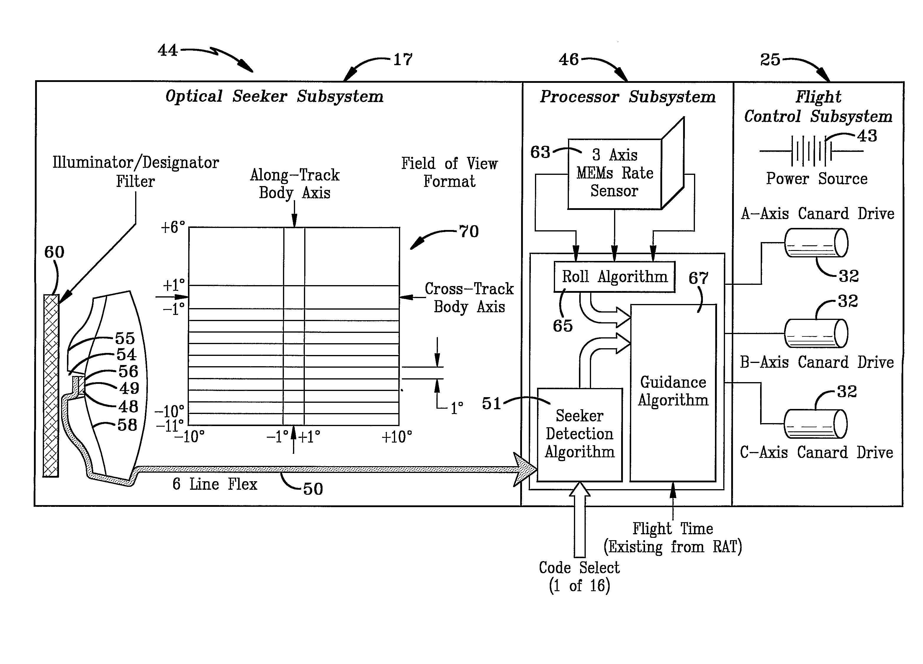
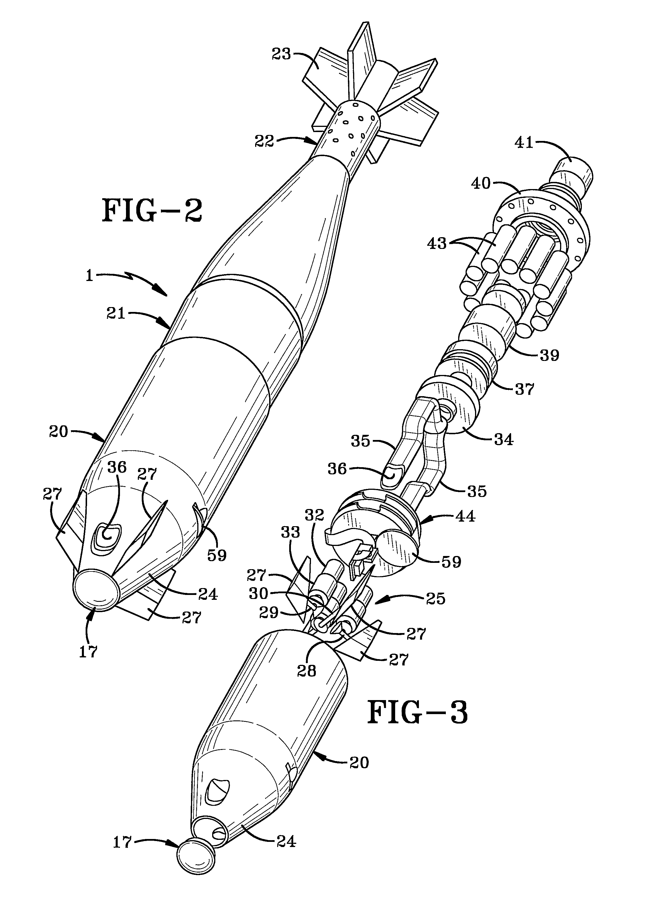
The present invention is a low cost optically guided munition that uses an optical seeker and related detection and tracking processor to home in on a target. It is a replacement for the current M734A1 and M783 fuse assemblies commonly used on certain mortar shells. The munition can be used against moving targets and improves accuracy and resulting reduction in CEP against stationary targets. It also utilizes a plurality of gyros to sense gravity induced overturning movement and provides a down reference. The guidance control assembly includes four canards, two of which are common to a single shaft with the other two being connected to independent shafts, each controlled by a stepper motor. The munition also includes an optical seeker for detecting an optical illuminator located at a target, a processor for generating steering commands, a canard assembly for changing the flight path of the munition, and a fuse mechanism for detonating the munition upon reaching the target.

Problems solved by technology

Furthermore, the optical seeker senses the target and looks off bore sight and uses a non-uniform pixel array.

Method used


Image

  • Optically Guided Munition
  • Optically Guided Munition
  • Optically Guided Munition

Examples


Embodiment Construction

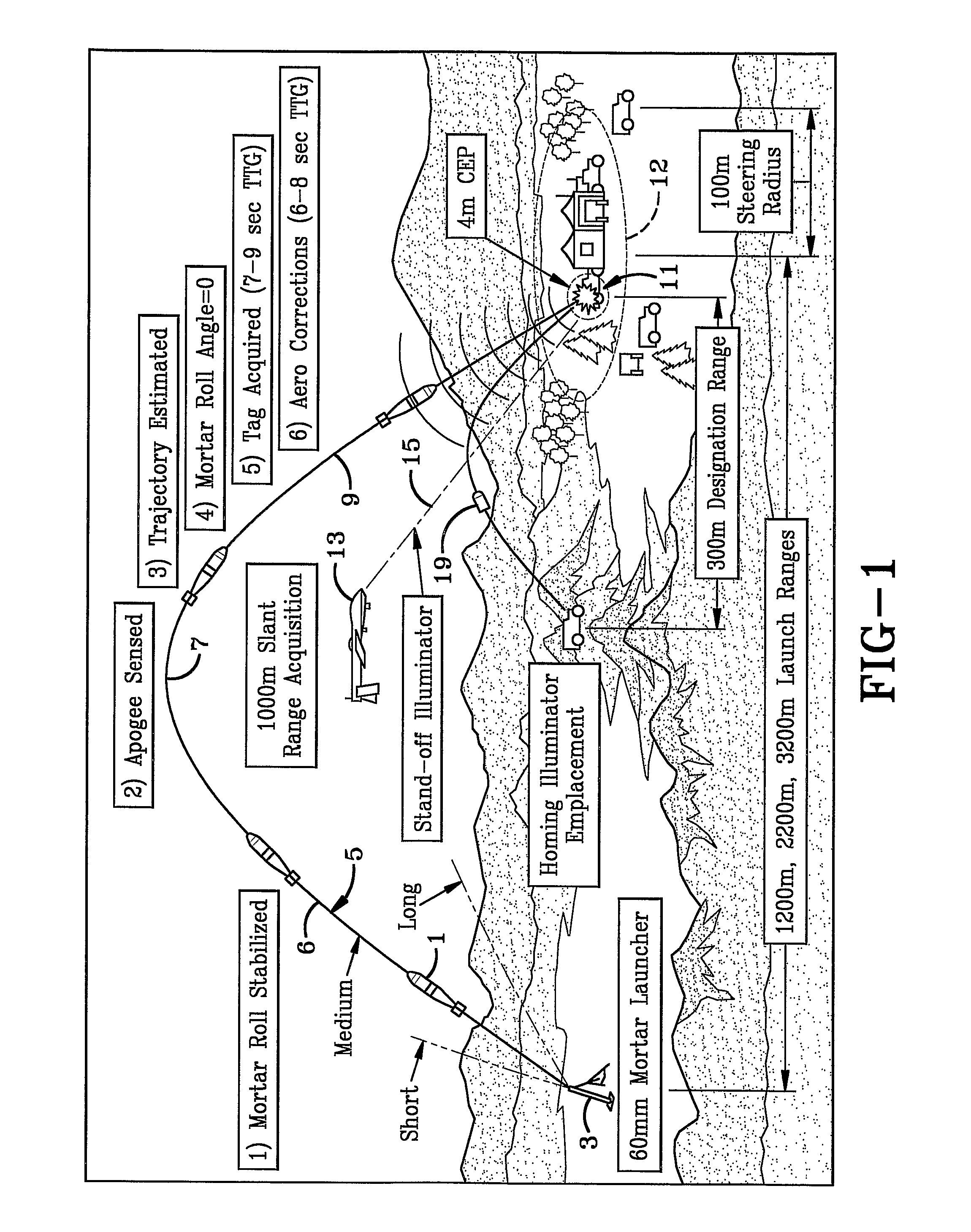
[0026] In general, FIG. 1 is a diagrammatic depiction of the proposed Concept of Operations for the optically guided munition of the present invention. The mortar or optically guided munition with optical smart fuse, results in improved accuracy, (<4 m CEP) under standard operating conditions, a significant improvement over current operational capability.

[0027] The optically guided munition broadly consists of an optical seeker, rate gyros, processor, battery pack, and a 3-axis motor driven canard assembly as shown in FIGS. 2-6. All of the components are integrated, along with existing fuse components such as a safe / arm mechanism, booster pellet, RAT (Ram Air Turbine), impact and delay components, into a minimal fore body extension which replaces a current M734A1 fuse housing. The mortar functions by being launched in the general vicinity of the target and upon reaching apogee, begins the descent portion of the ballistic flight path wherein the optical seeker acquires the target (i...


PUM


Abstract

The invention has a guidance and control system (44) which includes an optical seeker subsystem (17), a processor subsystem (46), a three-axis guidance control subsystem (25). The processor subsystem (46) includes a 3-axis MEMs rate sensor (63), a roll algorithm device (65), a seeker detection algorithm device (51), and a guidance algorithm device (67). The flight control subsystem (25) include three canard axis drives (32).

Description

CROSS REFERENCE TO RELATED APPLICATION [0001] This application claims rights under 35 USC 119(e) from U.S. application Ser. No. 60 / 650,719, filed Feb. 7, 2005; the contents of which are incorporated herein by reference.BACKGROUND OF THE INVENTION [0002] 1. Field of the Invention [0003] The present invention relates to armaments and more particularly to guided munitions. More particularly, the invention relates to a mortar shell having a low cost, effective guidance system incorporated therein to correct its ballistic guidance path to an illuminated target. [0004] 2. Background Information [0005] Mortars are one of the most commonly employed weapons in a ground combat unit. The traditional role of mortars has been to provide close and continuous fire support for maneuvering forces. Military history has repeatedly demonstrated the effectiveness of mortars. Their rapid, high-angle, plunging fires are invaluable against dug-in enemy troops and targets in defilade, which are not vulnerab...

Claims


Application Information

Patent Timeline
Patent Type & Authority Applications(United States)
IPC IPC(8): F41G7/00
CPCF41G7/222F41G7/226F42B15/01F42B10/64F41G7/2293
Inventor ZEMANY, PAUL D.CARLSON, MARK A.MAYNARD, JOHN A.
Owner BAE SYST INFORMATION & ELECTRONICS SYST INTERGRATION INC
Learn More