
Slip drive for leveling devices

Inactive Publication Date: 2007-09-06
GABRIEL EDWARD
View PDF27 Cites 30 Cited by
  • Summary
  • Abstract
  • Description
  • Claims
  • Application Information

AI Technical Summary

Benefits of technology

[0020] In accordance with one embodiment of the leveling device, a means may be connected to one end of the elevation shaft for protecting a nonuniform surface from damage by contact of the end of the shaft with the surface. In one embodiment, the surface protecting means may comprise a pad shaped as a round disk. In one embodiment, the elevation shaft is axially movable such that the pad may be completely retracted into the housing of the leveling device. In another embodiment, the pad may be rotably connected to the end of the elevation shaft to permit independent relative rotation between the pad and the shaft. The pad in yet another embodiment may be movably attached to the end of the elevation shaft to permit the pad to tilt at an angle relative to a plane perpendicular to the longitudinal axis of the shaft. In one embodiment, the angle may range from 0 to about 5 degrees.
[0041] According to another aspect of the invention, a leveling device with over-torque protection is provided that prevents installers from over-torqueing and damaging the leveling device when abnormally high resistance is encountered as input torque is applied to operate the leveling device with a tool. In one possible embodiment, the over-torque protection is provided by a compact, automatically-actuating torque-limiting mechanism. In another possible embodiment, the torque-limiting mechanism further provides an audible signal that alerts the installer to the fact that an abnormally high input torque situation is being encountered, such as when the upper or lower limits of the maximum range of possible vertical adjustment of the leveling device has been reached.

Problems solved by technology

The need to install and level objects on uneven or sloping floors has presented a long-standing problem, especially for various types of apparatuses including machines and appliances.
If all the legs do not contact the floor, many problems can develop.
For example, the outer cabinet and frame of an apparatus may become distorted over time due to nonuniform weight support, thereby impairing the proper operation of the apparatus.
In the case of a motorized apparatus such as a washing machine, inadequate contact of all its legs with the floor is especially problematic because these devices have a tendency to vibrate and “walk” across the floor if the floor is not level.
Annoying “rocking” problems with an apparatus may also result where the legs do not all contact the floor.
Moreover, installations that are not level may be aesthetically undesirable by the inability to match the heights of adjacent cabinets, other equipment, or work surfaces.
Obviously, this technique has numerous drawbacks.
First, the apparatus must be manually lifted while such shims are placed under the legs, thereby often requiring more than one installer.
This situation also increases the potential risk of back or other physical injuries to the installers.
Second, the shims are not permanently mounted to the apparatus legs and may shift over time or become completely dislodged.
This is especially problematic with motorized apparatuses which vibrate and “walk” as described above.
These manually adjustable supports, however, are still plagued by many of the problems encountered with the shim technique described above.
Furthermore, there is usually no way to access the rear legs for adjustment once the apparatus is slid into its final position because access is often not available from the rear or sides of the apparatus.
The manually adjustable leg design is also cumbersome to use, involving a time consuming trial and error approach to leveling the apparatus on uneven floors.
Other approaches have been used with limited success in an attempt to overcome the many problems of leveling objects on uneven floors.
Although the rear supports are adjustable from the front of the appliance, the mechanism is complicated and requires virtually all parts to be fabricated from metal.
Like many similar mechanisms, the manufacturing costs are high and they are prone to problems due to their complex design.
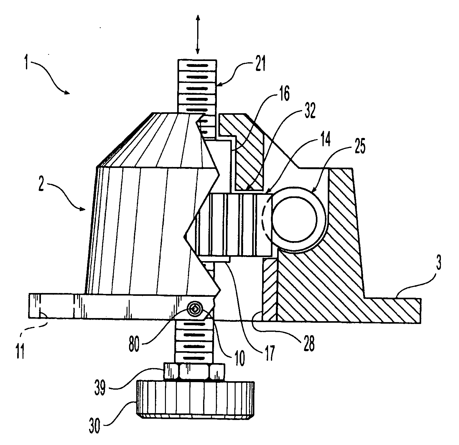
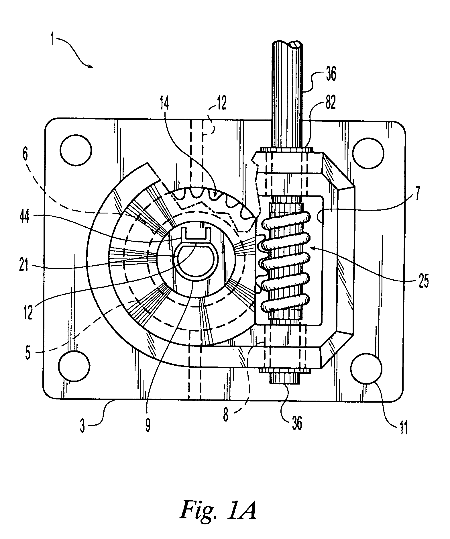
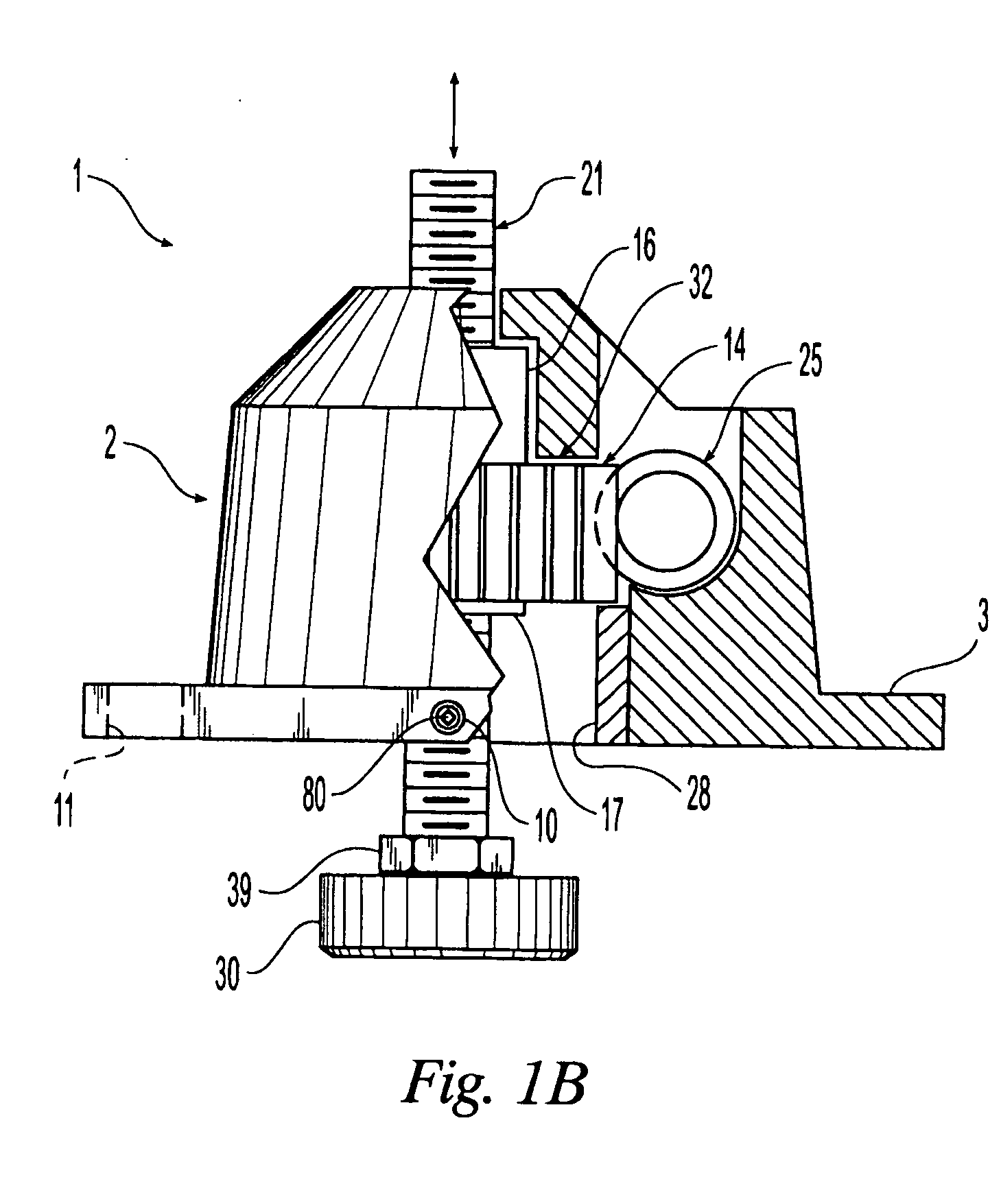
Although careful installers will typically not encounter problems, difficulties may occur if installers using power tools overtorque the leveling device by continuing to attempt to raise or lower the object to be leveled even after the vertical elevation shaft (described herein) of the leveling device has been either topped or bottomed out in its maximum range of vertical travel.
Despite the fact that significant resistance may encountered, some installers may continue to apply torque with the power tool and damage the leveling device causing for example the plastic gears to seize and bind.
This renders the leveling device inoperative so that the appliance or object attached to the device can no longer be lowered or raised to achieve a level and plumb installation.
This situation results in delays and additional expense.
The over-torqueing problem often cannot be solved by mere visual observation of the leveling device to determine if its full range of travel has been reached.
In other situations such as where leveling devices are installed on the rear of a kitchen appliance being placed against a wall, the rear of the appliance often cannot be observed by the installer once the appliance is positioned in it final location because of the presence of other appliances or cabinets on either side.

Method used


Image

  • Slip drive for leveling devices
  • Slip drive for leveling devices
  • Slip drive for leveling devices

Examples


Embodiment Construction

[0078] A first embodiment of the leveling device 1 is shown in FIGS. 1A& B as generally including a housing 2, a worm gear 25, a driven gear 14 having internal threads 61, and a threaded elevation shaft 21. A retaining collar 28 may be provided which holds the driven gear 14 inside the housing 2. A pad 30 may also be disposed on the lower end of the elevation shaft as shown. Leveling devices such as the present invention are installed on the bottom of an object, such as an appliance for example, where they function as a leg or support that may be adjusted to level the object when installed on a nonuniform surface. Basically, the leveling device 1 operates by rotating the worm gear 25 which causes concomitant rotations of the driven gear 14. The internal threads of the rotating driven gear 14 engage the threads of the elevation shaft 21. Since means are provided to prevent or restrain the shaft 21 from rotating in relation to the housing 2 (described hereafter), rotation of the drive...


PUM


Abstract

A device for leveling an object with over-torque protection. In one embodiment, the leveling device includes a housing including a worm gear, a driven gear, and an elevation shaft. The worm gear operably engages the driven gear, which in turn operably engages the elevation shaft. When the worm gear is rotated in opposite directions, concomitant rotations of the driven gear cause the elevation shaft to move axially up or down to provide leveling motions to an object to which the device is attached. In one embodiment, a torque-limiting mechanism includes a slip drive or clutch including (1) a drive member axially and rotatably disposed in the worm gear and having a first cam surface, (2) a driven member fixedly coupled to the worm gear and having a second cam surface complementary configured with the first cam surface, and (3) a biasing member urging the first cam surface into engagement with the second cam surface. The drive member is rotated by a manual or power tool to operate the leveling device. If the input torque required to raise or lower the object exceeds a predetermined limit, the slip clutch automatically actuates to prevent the worm gear from rotating to protect the leveling device.

Description

CROSS-REFERENCE TO RELATED APPLICATIONS [0001] This is a continuation-in-part of pending U.S. patent application Ser. No. 10 / 809,598, filed Mar. 24, 2004, entitled “Method for Leveling An Object,” which is a divisional of U.S. Pat. No. 6,729,590, filed Feb. 26, 2002, entitled “Leveling Device,” which claims the benefit of priority from U.S. provisional Patent Application No. 60 / 351,472, filed Jan. 23, 2002, entitled “Leveling Device,” all of which are incorporated herein by reference in their entirety.FIELD OF THE INVENTION [0002] The present invention generally relates to a leveling device, and more particularly to an improved device for leveling objects that includes a torque-limiting clutch mechanism that protects the leveling device from over-torqueing. BACKGROUND OF THE INVENTION [0003] The need to install and level objects on uneven or sloping floors has presented a long-standing problem, especially for various types of apparatuses including machines and appliances. Often floo...

Claims


Application Information

Patent Timeline
IPC IPC(8): F16M11/24
CPCF16M7/00
Inventor GABRIEL, EDWARD
Owner GABRIEL EDWARD
Features
  • Generate Ideas
  • Intellectual Property
  • Life Sciences
  • Materials
  • Tech Scout
  • Unparalleled Data Quality
  • Higher Quality Content
  • 60% Fewer Hallucinations
Learn More