Variable shape mirror and optical pickup device having the same

a technology of optical pickup and variable shape mirror, which is applied in the field can solve the problems of high manufacturing cost of variable shape mirror, increased manufacturing cost or the like, and the first type of variable shape mirror that is formed by laminating thin films may not have the performance that is required to a variable shape mirror, etc., and achieves the effect of low cost and low cos

Inactive Publication Date: 2007-09-06
FUNAI ELECTRIC CO LTD
View PDF1 Cites 12 Cited by
  • Summary
  • Abstract
  • Description
  • Claims
  • Application Information

AI Technical Summary

Benefits of technology

[0023]In addition, according to the seventh structure of the present invention, as to the optical pickup device equipped with the variable shape mirror having any one of the first to the sixth structure, correction of wave aberration can be performed appropriately because the variable shape mirror can deform the specular surface largely. In addition, since the variable shape mirror can be formed simply at low cost, a variable shape mirror that is capable of correcting wave aberration appropriately can be manufactured at low cost.

Problems solved by technology

However, the first type of variable shape mirror that is a type formed by laminating thin films may not have sufficient performance that is required to a variable shape mirror because that the piezoelectric body is a thin film and that piezoelectric characteristic of the piezoelectric body is inferior to the case of a bulk piezoelectric body.
In addition, lamination of thin films for manufacturing the variable shape mirror requires a sophisticated manufacturing technique, so there may be problems of high manufacturing cost of the variable shape mirror and a heavy load on manufacturing works.
Therefore, there is a problem of an increase of manufacturing cost or the like because a loss of material is generated in a cutting process.

Method used


Image

  • Variable shape mirror and optical pickup device having the same
  • Variable shape mirror and optical pickup device having the same
  • Variable shape mirror and optical pickup device having the same

Examples


Embodiment Construction

[0029]Now embodiments of the present invention will be described with reference to the attached drawings. At this point, the embodiments described here are merely examples and that the present invention should not be limited to these embodiments.

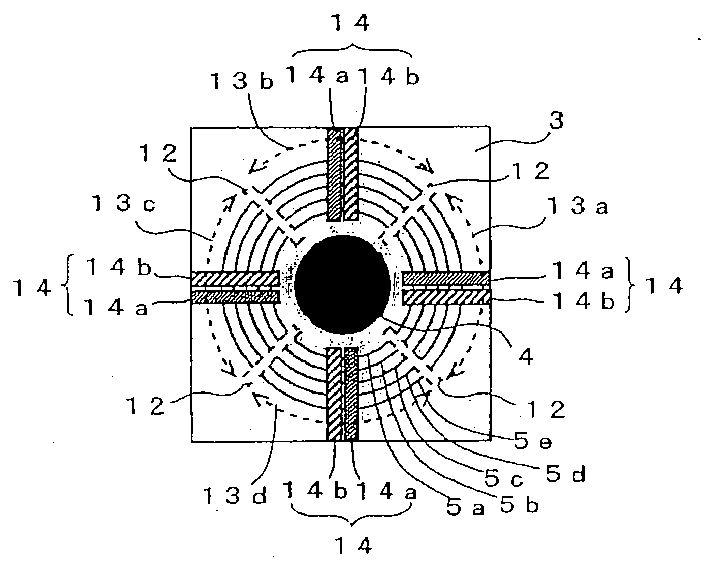
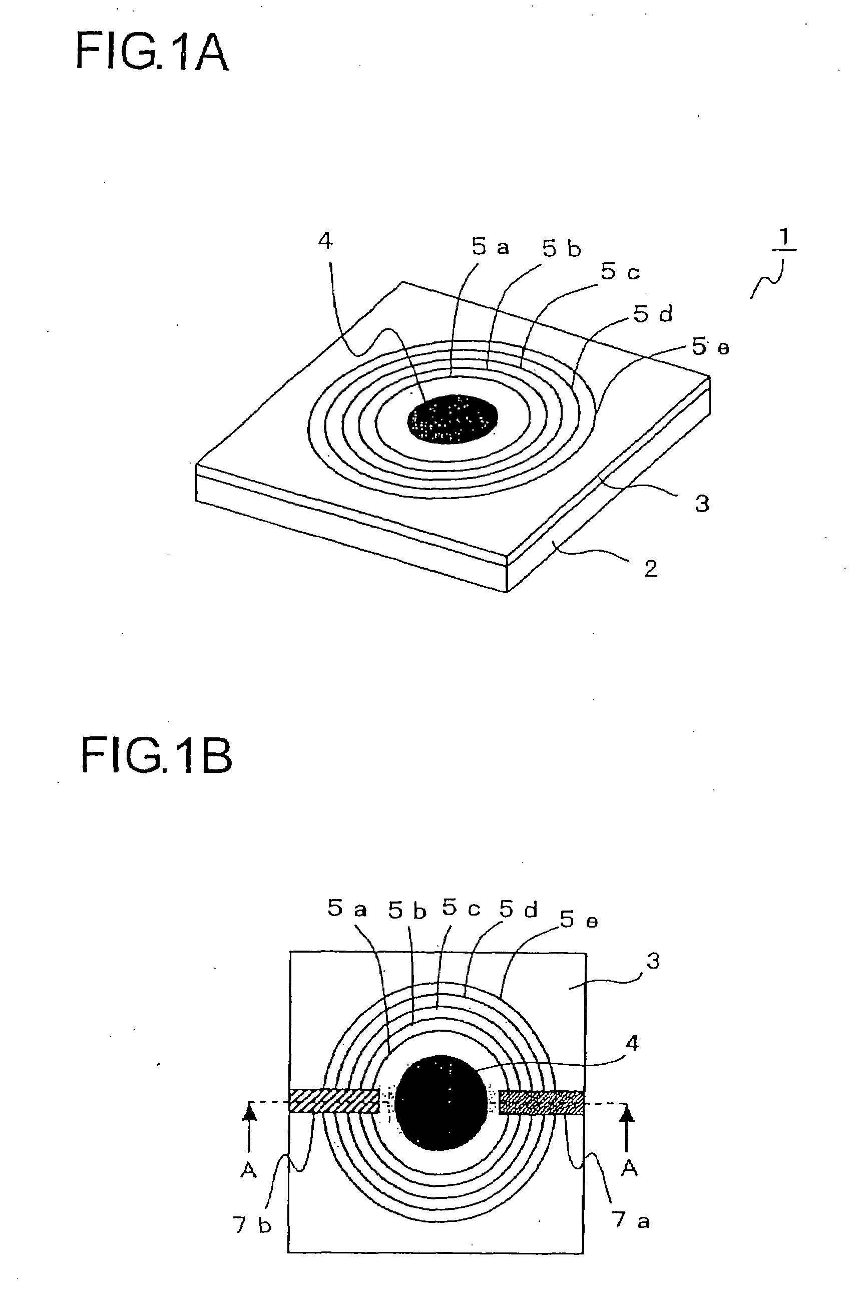
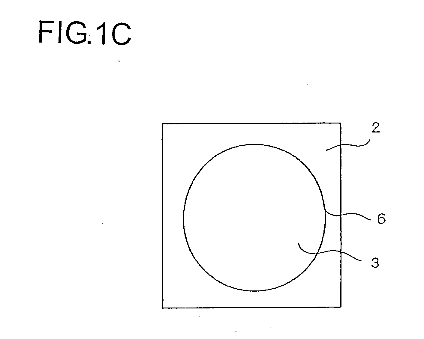
[0030]FIGS. 1A-1C are schematic diagrams to show a structure of a variable shape mirror according to a first embodiment. FIG. 1A is a perspective view to show a structure of a variable shape mirror 1 according to the first embodiment, FIG. 1B is a top view to show the structure of the variable shape mirror 1 according to the first embodiment, and FIG. 1C is a bottom view to show the structure of the variable shape mirror 1 according to the first embodiment. At this point, common electrodes 7a and 7b are shown in FIG. 1B but are omitted in FIG. 1A.

[0031]The variable shape mirror 1 is made up of a substrate 2 and a piezoelectric body 3 mainly. First, a piezoelectric body 3 will be described. The piezoelectric body 3 has a structure like a plat...


PUM


Abstract

The variable shape mirror (1) includes a substrate (2) and a bulk piezoelectric body (3). On the piezoelectric body (3), a specular surface (4) is formed, and further a plurality of grooves (5a-5e) are formed at a predetermined interval. The grooves (5a-5e) are arranged so as to surround the specular surface (4) and filled with the conductive members. The conductive members embedded in the grooves (5a-5e) are connected electrically to one of a pair of common electrodes (7a and 7b) that is disposed to cross the grooves (5a-5e) and are formed to be electrodes having different polarities in alternating manner in the direction from the inner side to the outer side of the grooves (5a-5e).

Description

[0001]This application is based on Japanese Patent Application No. 2006-056327 filed on Mar. 2, 2006, the contents of which are hereby incorporated by reference.BACKGROUND OF THE INVENTION[0002]1. Field of the Invention[0003]The present invention relates to a variable shape mirror that is provided to an optical device such as an optical pickup device. In particular, the present invention relates to a variable shape mirror that is formed by using a bulk material having piezoelectric characteristics. In addition, the present invention relates to an optical pickup device having a variable shape mirror.[0004]2. Description of Related Art[0005]Conventionally, there are many reports concerning a variable shape mirror that can alter a shape of its specular surface, and there are roughly two types of variable shape mirrors as follows.[0006]A first type is a variable shape mirror that is formed by laminating thin films. This type of variable shape mirror having a structure in which thin film...

Claims


Application Information

Patent Timeline
Patent Type & Authority Applications(United States)
IPC IPC(8): G02B5/08
CPCG02B26/0825G11B7/08564G11B2007/0006G11B7/1362G11B7/13927G11B7/1275
Inventor TANAKA, FUMINORI
Owner FUNAI ELECTRIC CO LTD
Why Eureka
Try Eureka