Imaging System And Image Processing Program

a technology of image processing and image system, applied in the field of image processing system and image processing program, can solve the problems of fixed pattern noise, random noise at the imaging device and analog circuit, and dynamic change of noise quantity

Inactive Publication Date: 2007-09-06
OLYMPUS CORP
View PDF3 Cites 19 Cited by
  • Summary
  • Abstract
  • Description
  • Claims
  • Application Information

AI Technical Summary

Benefits of technology

[0006] (1) To accomplish the aforesaid objects, the present invention provides an imaging system adapted to process a digitalized signal from an imaging device, characterized by comprising a noise estimation means for estimating a quantity of noise in said signal and an image processing means for implementing image processing based on said quantity of noise. The invention of (1) is embodied as the first, the second, and the third embodiment shown in FIGS. 1-16. The noise estimation means is equivalent to the noise estimation block 106 shown in FIGS. 1 and 2, the noise estimation block 1006 shown in FIGS. 3 and 4, and the noise estimation block 5006 shown in FIGS. 5 and 6. The image processing means is equivalent to the noise reduction block 105 shown in FIGS. 1 and 2, and the noise reduction block 1005 shown in FIGS. 3-6. In a preferable embodiment of the imaging system according to the invention of (1), the quantity of noise is estimated by the noise estimation block 106 in the first embodiment of FIG. 1, the noise estimation block 1006 in the second embodiment of FIG. 3, and the noise estimation block 5006 in the third embodiment of FIG. 5, and image processing is implemented on the basis of the estimated noise quantity. With the invention of (1), the quantity of noise is precisely estimated, and image processing is implemented on the basis of it. The precise estimation of noise quantity ensures image processing capable of generating high-definition images.

Problems solved by technology

As represented by defective pixels or the like, the fixed pattern noise results chiefly from an imaging device.
On the other hand, the random noise occurs at the imaging device and analog circuit, having characteristics close to white noise ones.
However, the noise quantity changes dynamically with temperatures at a taking time, exposure times, gains, etc.
In other words, the precision of noise quantity estimation is poor, because of inability to be adaptive to that function fit for the noise quantity at the taking time.
For that precise noise quantity estimation, there are high-precision parts required to acquire elements like signal value levels, ISO sensitivities and color signals, which result in some costs added to a hardware system.

Method used


Image

  • Imaging System And Image Processing Program
  • Imaging System And Image Processing Program
  • Imaging System And Image Processing Program

Examples


first embodiment

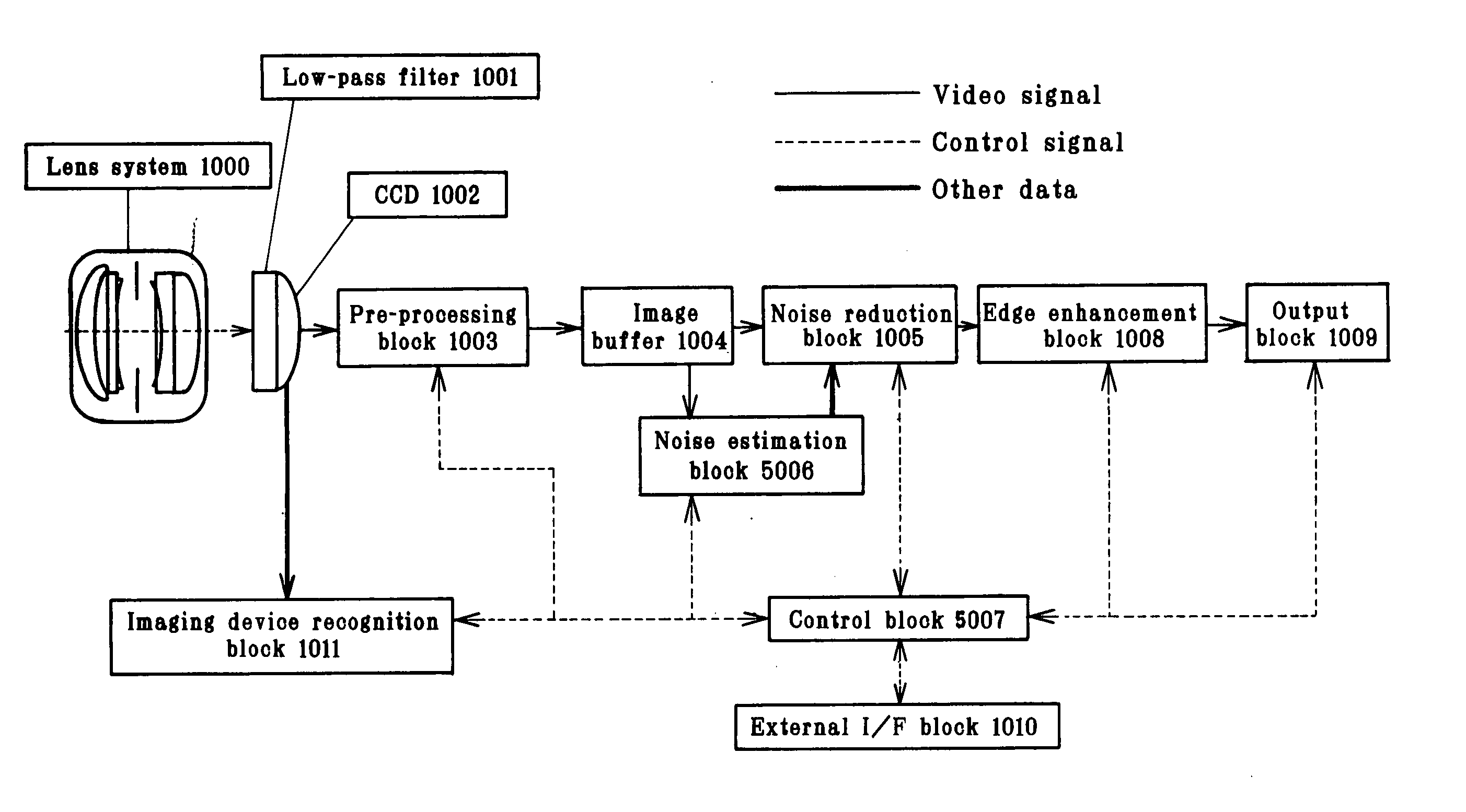
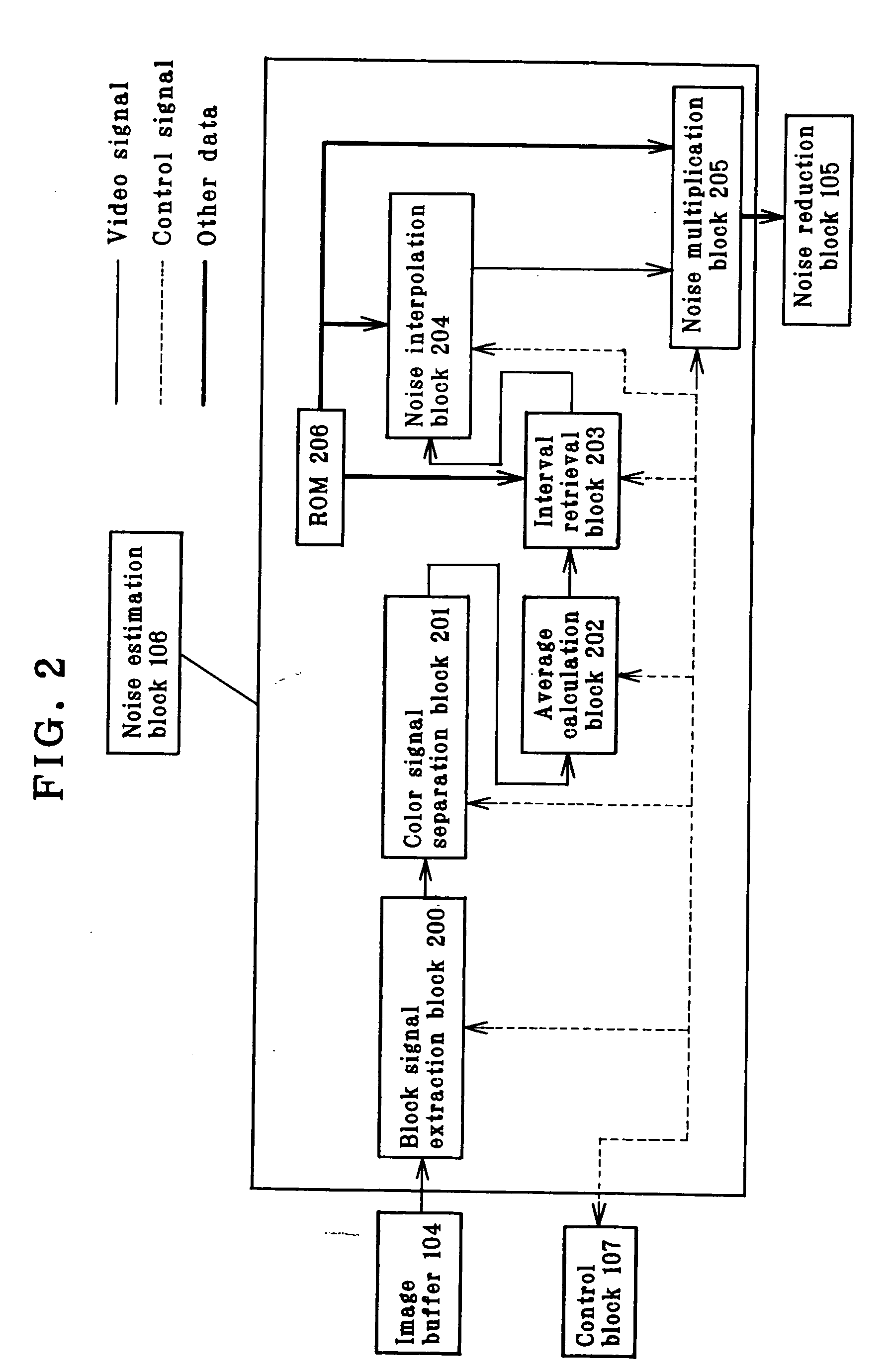
[0054] In the embodiment here, there is one reference noise model as in the first embodiment, but there are correction coefficients to keep up with different imaging devices. And then, the type of the imaging device CCD 1002 used is detected by the imaging device recognition block 1011 of FIG. 3 to extract out of correction coefficients (M) in ROM 2005 of FIG. 4 the one corresponding to that imaging device by way of the control block 1007. For instance, an example of correction coefficients corresponding to three different imaging devices is represented by formula (7).

M[3]={M1, Imaging Device 1

M2, Imaging Device 2

M3} Imaging Device 3  (7)

[0055] For the reference noise model, data approximated to a broken line are stored in ROM 2005, as in the first embodiment. A specific data form comprises 8 representative points of the signal value level vs. noise quantity and 7 points of slope indicative of each representative point and a direction of an interval between representative points....

second embodiment

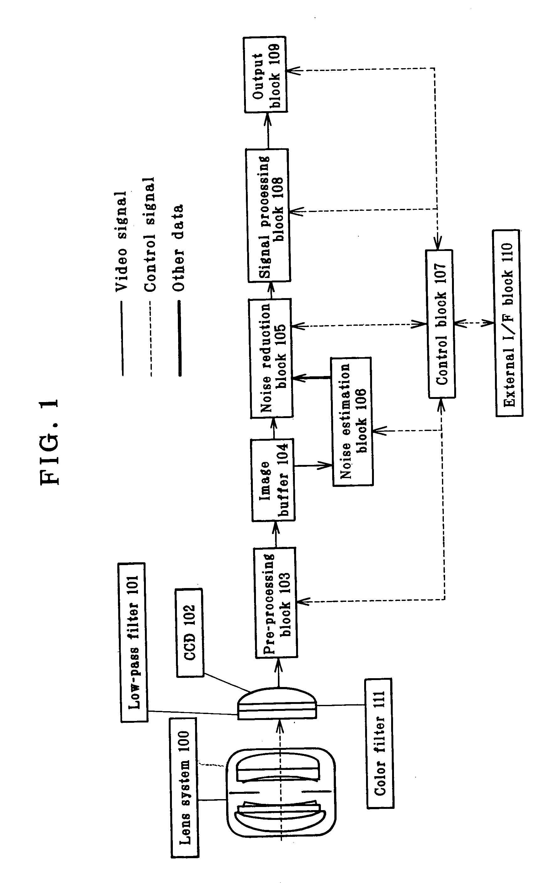
[0066]FIG. 9 is illustrative of one example of the architecture of the noise reduction block 1005 that is made up of a filtering block 3000 and a buffer block 3001. The image buffer 1004 is connected to the buffer block 3001 via the filtering block 3000, and the noise estimation block 5006 is connected to the filtering block 3000. The control block 5007 is bidirectionally connected to the filtering block 3000 and the buffer block 3001. The buffer block 3001 is connected to the edge enhancement block 1008. The filtering block 3000 uses the quantity of noise and the average value transmitted from the noise estimation block 1006 to apply noise reduction processing to video signals at the image buffer 1004. The noise reduction processing and the edge enhancement processing are the same as in the

[0067] With the above arrangement, whatever white-and-black imaging devices having a variety of different noise characteristics are used, it is possible to estimate the quantity of noise dependin...


PUM


Abstract

Acquired video signals are forwarded to pre-processing block (103) for sampling, gain amplification and A/D conversion, and then forwarded to image buffer (104). Video signals in image buffer (104) are forwarded to noise estimation block (106). On the basis of taking conditions, video signals and a reference noise model, noise estimation block (106) works out the quantity of noise per ISO sensitivity, and per color signal. The calculated noise quantity is forwarded to noise reduction block (105). On the basis of the noise quantity estimated at the noise estimation block (106), the noise reduction block (105) applies noise reduction processing to video signals in image buffer (104), and video signals after noise reduction processing are forwarded to signal processing block (108).

Description

TECHNICAL ART [0001] The present invention relates to an imaging system and an image processing program, wherein the quantity of random noise ascribable to an imaging device is estimated on the basis of dynamically changing factors such as signal value levels, ISO sensitivities and color signals, thereby achieving high-precision reduction of noise components only. BACKGROUND ART [0002] Noise components included in digitalized signals obtained from an imaging device, its associated analog circuit and an A / D converter are generally broken down into fixed pattern noise and random noise. As represented by defective pixels or the like, the fixed pattern noise results chiefly from an imaging device. On the other hand, the random noise occurs at the imaging device and analog circuit, having characteristics close to white noise ones. [0003] Regarding the random noise, for instance, JP-A 2001-157057 shows a technique wherein the quantity of noise is turned into a function with respect to a s...

Claims


Application Information

Patent Timeline
Patent Type & Authority Applications(United States)
IPC IPC(8): G06K7/00H04N5/335H04N5/232H04N5/357H04N5/378H04N9/04
CPCH04N5/2352H04N9/045H04N5/357H04N23/72H04N25/60H04N23/843
Inventor WEN, CHENGGANG
Owner OLYMPUS CORP
Why Eureka
Try Eureka