Collapsible flat rack

a flat rack and collapsible technology, applied in the field of collapsible flat racks, can solve the problems of inability to easily impact the exposed cargo of the top corner, inability to prevent the passage of passengers and cargo, and the risk of attendant damag

Inactive Publication Date: 2007-09-06
CLIVE SMITH MARTIN
View PDF26 Cites 20 Cited by
  • Summary
  • Abstract
  • Description
  • Claims
  • Application Information

AI Technical Summary

Problems solved by technology

However, a problem arises in using 40 ft spreaders to handle 45 ft containers within 45 ft span cell guides.
In doing so, the spreader and cargo can come into inadvertent contact, with attendant damage risk.
An open frame flat rack has no roof, so a 40 ft s

Method used


Image

  • Collapsible flat rack
  • Collapsible flat rack
  • Collapsible flat rack

Examples


Embodiment Construction

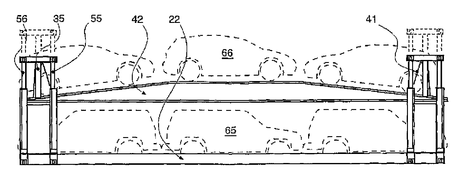
[0069]FIG. 1 depicts a typical known collapsible container 50 of some 40 ft length or span, with a platform base deck 10 surmounted at each end by a pair of opposed corner posts 12.

[0070] Upon each corner post 12 is a top capture and handling fitting 13, such as a hollow rectangular box with apertures on three outermost sides for a standard so-called ‘twistlock’.

[0071] Similarly, a bottom capture and handling fitting 15 is located at each four bottom corners of flat rack 50.

[0072]FIG. 1 depicts three small cars 16 disposed in tandem upon base deck platform 10 of flat rack 50.

[0073] Overall flat rack 50 height (distance of top fitting 13 above ground) is limited by fixed end support post frames 46.

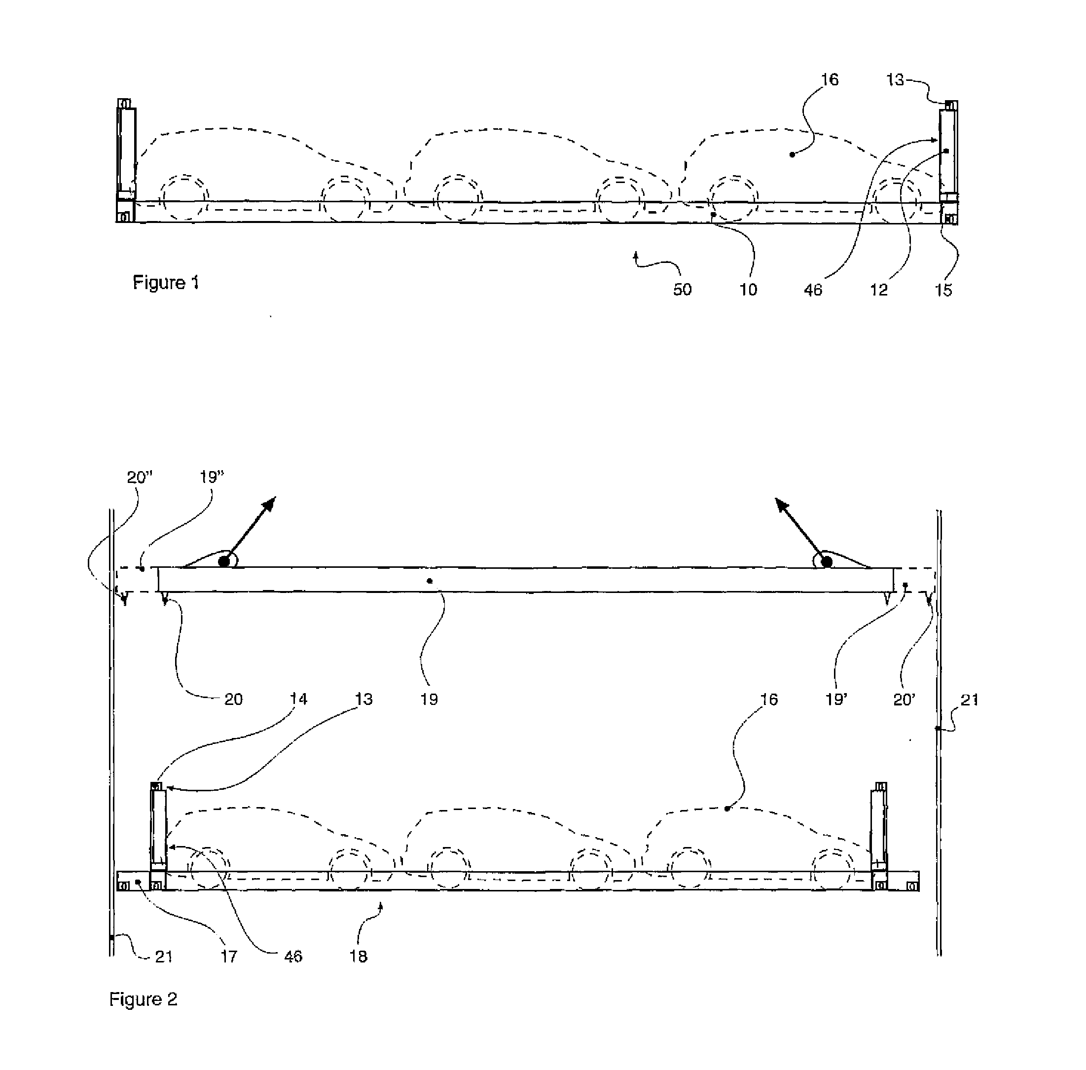
[0074]FIG. 2 depicts a flat rack 18 similar to flat rack 50, but with base deck stub extensions 17 at each end—taking overall length typically to some 45 ft or more.

[0075] However, support posts 46 remain at a 40 ft span.

[0076] Suspended above flat rack 18 is a crane lift spreader 19...


PUM


Abstract

A collapsible dual deck platform deck or flat rack container, adapted for vehicle cargo, has dual (40 fit and 45 ft) span capture and handling fittings upon twin or joint adjustable height corner support post modules, foldable transversely inward to overlie one another at platform deck ends, with an underlying hinged end gate upon one post; post modules feature telescopic rams with a pulley traveller carrying a cable lift to a movable deck.

Description

CROSS-REFERENCE TO RELATED APPLICATIONS [0001] This application is a divisional of U.S. patent application Ser. No. 10 / 533,987 filed May 4, 2005 entitled: “Collapsible Flat Rack”. This application also claims domestic priority from PCT Application Number PCT / GB03 / 04805, which claims priority from United Kingdom Patent Application Number 0226012.3 all fully incorporated herein by reference.BACKGROUND OF THE INVENTION [0002] Collapsible Flat Rack Collapsible platform deck, or so-called ‘flat rack’, containers adapted for carrying (road) vehicles, in particular cars, are known. [0003] Typically the flat rack is some 40 ft long, with a deck capacity for 2 or 3 cars in tandem. [0004] Recent developments in containers have allowed an increase in standardised length from 40 ft to 45 ft—and in some countries even longer at 58 ft. [0005] Handling devices and transport vehicles for the former 40 ft standard containers have hitherto been adapted to carry only 40 ft lengths. [0006] Nowadays, lo...

Claims


Application Information

Patent Timeline
IPC IPC(8): B60P3/08B65D85/68B65D88/00B65D88/02B65D88/12B65D88/52B65D90/00
CPCB65D88/005B65D88/022B65D2585/6867B65D88/522B65D90/0026B65D88/129
Inventor CLIVE-SMITH, MARTIN
Owner CLIVE SMITH MARTIN
Why Eureka
Try Eureka