Unified workstation for virtual craniofacial diagnosis, treatment planning and therapeutics

a virtual craniofacial and workstation technology, applied in the field of computerized techniques for diagnosing and planning medical and dental treatment of human patients, can solve the problems of time-consuming and labor-intensive, no guarantee of the good results of treatment, and unscientific process, so as to achieve the best position of teeth, create multiple morphed models, and analyze quickly

Inactive Publication Date: 2007-09-06
ORAMETRIX
View PDF13 Cites 71 Cited by
  • Summary
  • Abstract
  • Description
  • Claims
  • Application Information

AI Technical Summary

Benefits of technology

[0014] 1) Firstly, automatically, and / or with the aid of operator interaction, the set of instructions includes instruction that operate to superimpose the first set of digital data and the second set of digital data so as to provide a composite, combined digital representation of the craniofacial anatomical structures in a common. Preferably, but not necessarily, this representation will be a three-dimensional representation in a common 3D coordinate system. This representation is referred to herein occasionally as a “virtual patient model.” In this aspect, the techniques of creation of a 3-D model disclosed in the patent application of Rohit Sachdeva et al., Ser. No. 09 / 560,641 filed Apr. 28, 2000 may be employed. Scaling techniques may be used to scale the data from one set of images to the other so as to created correctly scaled composite model that accurately reflects the patient's anatomy.
[0018] The software further includes instructions providing the user with tools to manipulate the position of the virtual teeth in the three-dimensional virtual model of the dentition relative to other anatomical structures of the patient and to visualize the effect of proposed changes in tooth position on the facial appearance of the patient. Thus, the tools thereby provide the user with the ability to design with the computer a desired three-dimensional configuration of the virtual teeth while viewing the effect of changing tooth position on the visual appearance of the face of the patient.
[0022] In the above simulations, the teeth of the patient are preferably represented as individual tooth models that are moveable relative to each other. The clinician is provided with tools to manipulate their position for diagnostic and treatment-planning purposes. Moreover, the tools provide the user the ability to simulate changes in the position or shape of the jaw, tooth or teeth, and the movement of such structures and the skull movement, and to visually observe the effect of such simulated changes on the patient's face and smile. This provides for powerful tools for study of proposed treatments for the patient. Similarly, the patient's desired feature and smile can be simulated on the user interface, and from that desired feature and smile it is possible to automatically back solve for the required jaw, and / or tooth movements or changes needed to provide that desired result, simply by comparing “before” and “after” positions of the jaw, tooth and / or skull positions.
[0023] Thus, in the broader aspects, we have invented an apparatus for assembling a virtual patient model from various data sources including 3D scanners, X-rays and 2D color camera. We have also invented a unique method for studying the interaction of craniofacial structures by varying the smile and age of the patient and the position of the teeth. For example, for the desired smile on the face, the best position of the teeth is calculated. On the other hand, the effect of various positions of the teeth on the smile can also be studied. Furthermore, we have invented a unique method for treatment planning of craniofacial structures based on the virtual patient model. By modifying various parameters, we can create multiple morphed models and multiple treatment plans quickly and reliably.
[0024] In presently preferred embodiments, the workstation also provides capabilities for integrating two and three-dimensional image data from a variety of sources, accessing treatment planning tools (software) either directly in the workstation or by furnishing data to a separate workstation that has such software, and integrating the resulting appliance design and treatment plan in a form compatible with the computer systems of diverse appliance manufacturers. In essence, the workstation facilitates a common platform by which a practitioner can integrate the acquisition of data, the treatment plan, and the appliance design and manufacture into one seamless system.

Problems solved by technology

Generally, this process is not very scientific, and it is time consuming and requires experience.
There is no guarantee how good the results of the treatment will be.
This approach also lacks reliability, reproducibility and precision.

Method used


Image

  • Unified workstation for virtual craniofacial diagnosis, treatment planning and therapeutics
  • Unified workstation for virtual craniofacial diagnosis, treatment planning and therapeutics
  • Unified workstation for virtual craniofacial diagnosis, treatment planning and therapeutics

Examples


Embodiment Construction

[0049] General Description

[0050] A unified workstation environment and computer system for diagnosis, treatment planning and delivery of therapeutics, especially adapted for treatment of craniofacial structures, is described below. In one possible example, the system is particularly useful in diagnosis and planning treatment of an orthodontic patient. Persons skilled in the art will understand that the invention, in its broader aspects, is applicable to other craniofacial disorders or conditions.

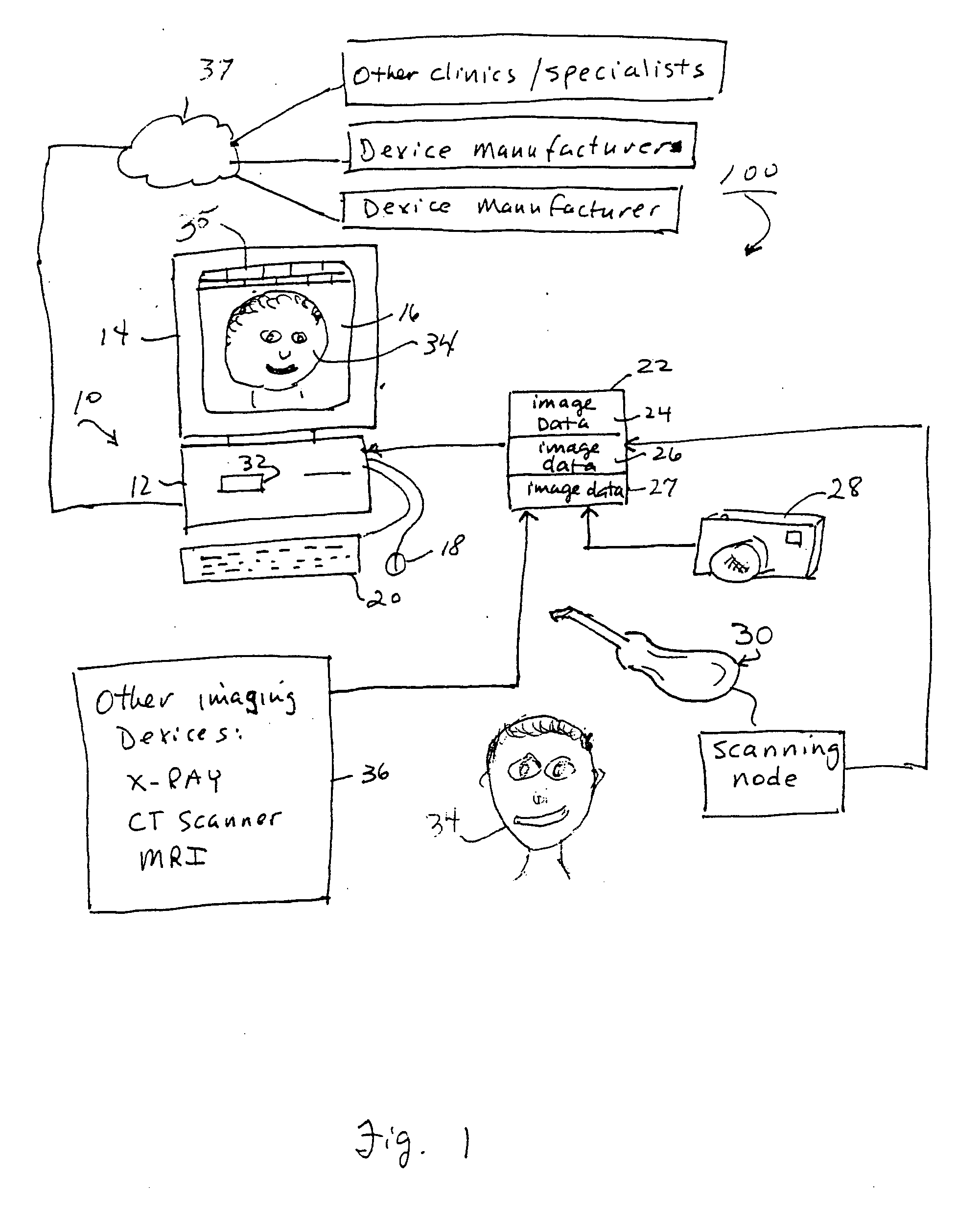
[0051] A presently preferred embodiment is depicted in FIG. 1. The overall system 100 includes a general-purpose computer system 10 having a processor (CPU 12) and a user interface 14, including screen display 16, mouse 18 and keyboard 20. The system is useful for planning orthodontic treatment for a patient 34. In another example, the system is particularly useful in planning therapeutics and designing customized appliances for the patient. In still another example, the system is particul...


PUM


Abstract

An integrated system is described in which digital image data of a patient, obtained from a variety of image sources, including CT scanner, X-Ray, 2D or 3D scanners and color photographs, are combined into a common coordinate system to create a virtual three-dimensional patient model. Software tools are provided for manipulating the virtual patient model to simulation changes in position or orientation of craniofacial structures (e.g., jaw or teeth) and simulate their affect on the appearance of the patient. The simulation (which may be pure simulations or may be so-called “morphing” type simulations) enables a comprehensive approach to planning treatment for the patient. In one embodiment, the treatment may encompass orthodontic treatment. Similarly, surgical treatment plans can be created. Data is extracted from the virtual patient model or simulations thereof for purposes of manufacture of customized therapeutic devices for any component of the craniofacial structures, e.g., orthodontic appliances.

Description

RELATED APPLICATIONS [0001] This application claims priority benefits pursuant to 35 U.S.C. § 120 as a continuation-in-part of application Ser. No. 10 / 340,404 filed Jan. 9, 2003, which is a continuation of application Ser. No. 09 / 560,641, filed Apr. 28, 2000, now U.S. Pat. No. 6,512,994, which is a continuation-in-part of application Ser. No. 09 / 452,034 filed Nov. 30, 1999, abandoned. This application also claims priority benefits pursuant to 35 U.S.C. § 120 as a continuation-in-part of application Ser. No. 09 / 835,039 filed Apr. 13, 2001, pending. The entire contents of the related applications are fully incorporated by reference herein. [0002] This application is also related to a patent application filed on the same date as this application, inventors Rohit Sachdeva et al., entitled INTERACTIVE UNIFIED WORKSTATION FOR BENCHMARKING AND CARE PLANNING, Ser. No. ______ attorney docket no. 03-318, the entire contents of which are incorporated by reference herein. [0003] This applicatio...

Claims


Application Information

Patent Timeline
Patent Type & Authority Applications(United States)
IPC IPC(8): A61C7/00A61BA61C3/00A61C7/14A61C8/00A61C13/00A61F2/30
CPCA61C7/00A61C7/002A61C7/146A61F2002/30953A61C9/004A61C13/0004A61C2007/004A61C8/009A61C9/0046A61C9/0086G16H20/40
Inventor SACHDEVA, ROHITTANEJA, SANJEEVSPORBERT, PEERGETTO, PHILLIPMAETZEL, STEPHANIMGRUND, HANSABRAHAM, CHARLES L.
Owner ORAMETRIX
Why Eureka
Try Eureka