Electrical connection construction

Active Publication Date: 2007-09-06
SUMITOMO WIRING SYST LTD
View PDF3 Cites 58 Cited by
  • Summary
  • Abstract
  • Description
  • Claims
  • Application Information

AI Technical Summary

Benefits of technology

[0015]The intermediate terminal is fixed in the waiting side housing and the waiting side housing is mounted in the motor casing. The intermediate terminal and the motor side terminal may be displaced from each other due to a dimensional error or the like. The prior art arrangement requires movement of the motor side terminal towards the intermediate terminal to achieve the required alignment. However, the motor side terminal is connected with a motor coil or the like and cannot be repositioned freely. Accordingly, the subject invention has the busbar between the motor side terminal and the intermediate terminal. One of the motor side terminal and the busbar includes the error compensating portion that compensates for the displacement. Th

Problems solved by technology

The bolt inserting operation becomes burdensome if the bolt ins

Method used


Image

  • Electrical connection construction
  • Electrical connection construction
  • Electrical connection construction

Examples


Embodiment Construction

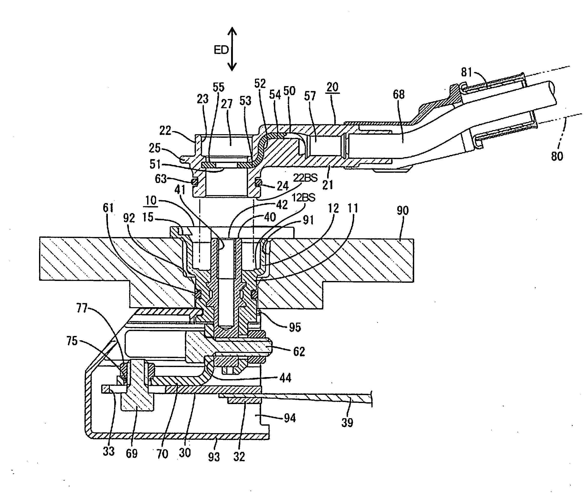
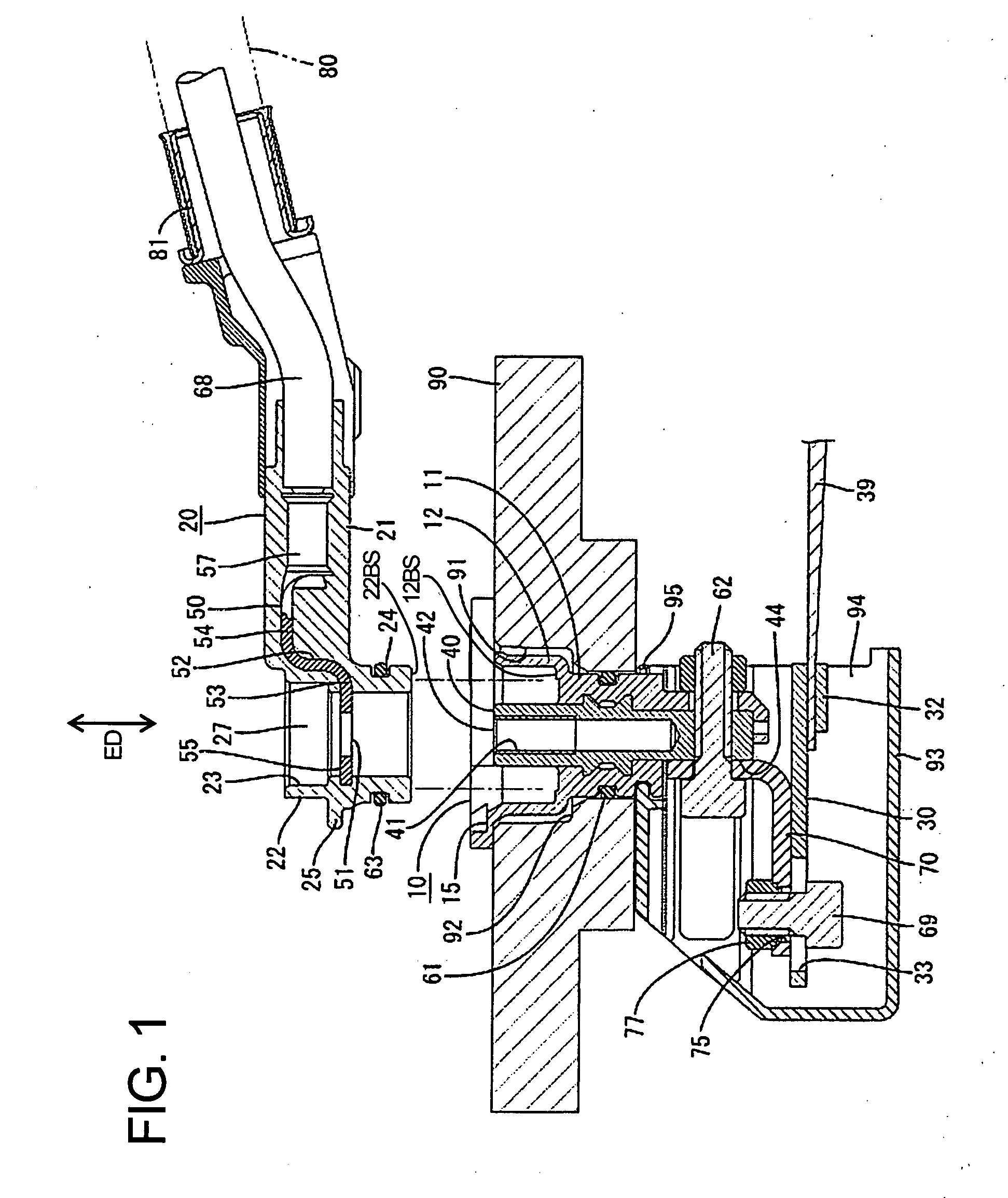
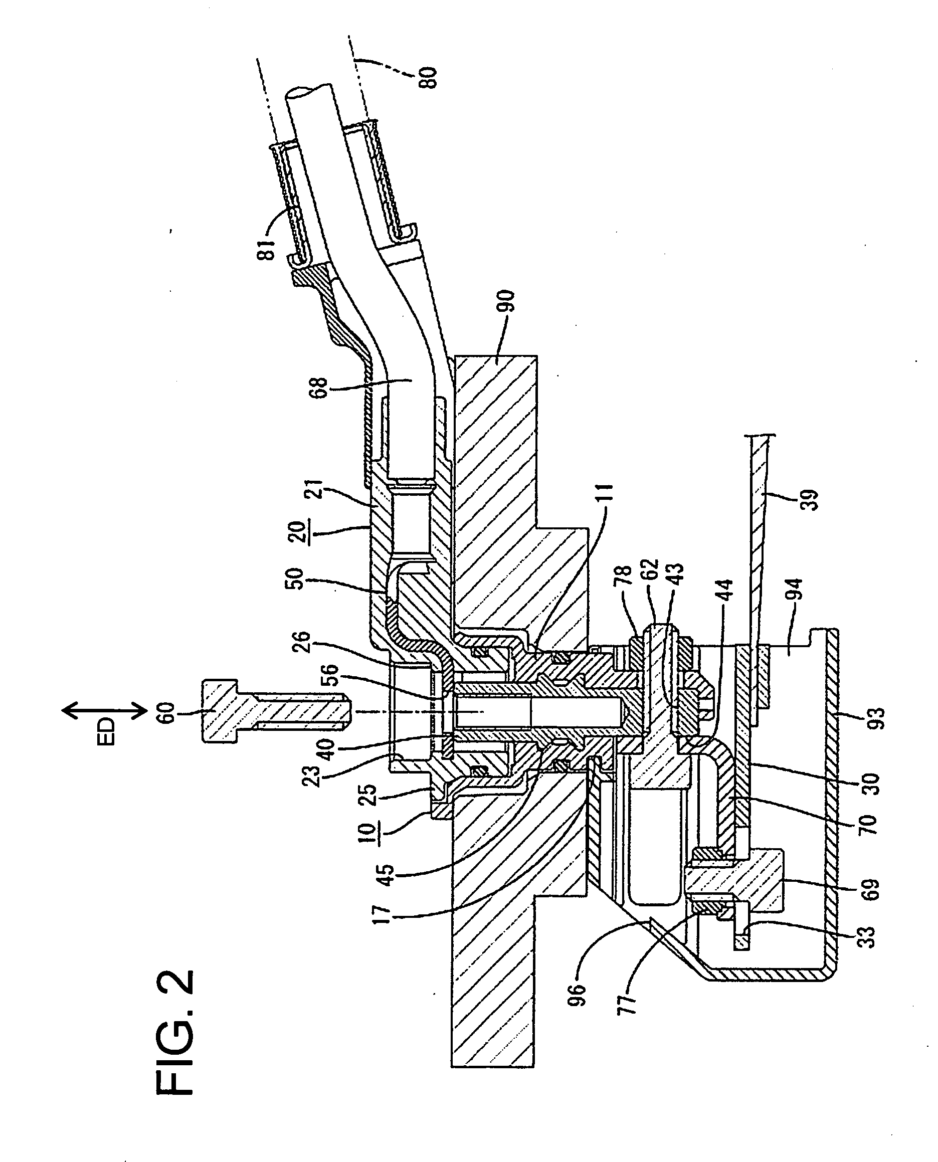
[0026]An electrical connection construction in accordance with the invention is illustrated in FIGS. 1 to 8 and is intended for supplying power to a motor installed in a hybrid vehicle or the like. The construction is used with a motor casing 90 made of metal or alloy for accommodating a stator of an unillustrated motor. A mount hole 91 penetrates a wall of the motor casing 90 vertically along an extension direction ED to provide communication between the inside and outside of the motor casing 90.

[0027]A step 92 is formed substantially in a middle part of the mount hole 91 of the motor casing 90 along the extension direction ED of the hole surface. An upper opening above the step 92 has a large diameter and a lower opening below the step 92 has a small diameter. A waiting side housing 10 is fit into the mount hole 91 of the motor casing 90 from above and along the extension direction ED. The waiting side housing 10 is made of e. g. a synthetic resin that is molded unitarily around t...


PUM


Abstract

Power feed terminals (50) are held in movable side housings (20), and intermediate terminals (40) are held in a waiting side housing (10). Each intermediate terminal (40) includes a power-feed side contact (42) and a motor side contact (44). A connection surface (12BS) of the waiting side housing (10) is exposed at the outer surface of a motor casing (90), and the power-feed side contacts (42) of the intermediate terminals (40) are exposed in the connection surface (12BS) of the waiting side housing (10). By connecting the housings (10, 20), contacts (51) of the power feed terminals (50) are placed on the power-feed side contact portions (42) and bolts (60) are inserted through these contacts placed one over the other to fix the terminals (40, 50) together.

Description

BACKGROUND OF THE INVENTION[0001]1. Field of the Invention[0002]The invention relates to an electrical connection construction for a motor.[0003]2.Description of the Related Art[0004]Japanese Unexamined Patent Publication No. 2001-25187 discloses a means for connecting a power supply cable to a motor in a hybrid vehicle or the like that uses a combination of an engine and a motor as a source of power. The connector has a motor side terminal connected with an end of a motor conductor from a stator coil. A power feed terminal of a power feed cable is placed on the motor side terminal and the two terminals are fixed by a bolt. The bolt provides good connection reliability by strongly pressing both terminals together.[0005]The above-described connection case requires the bolt insertion holes of the power feed terminal and the motor side terminal to be aligned. The terminals then must be fixed by hand so as not to move while keeping an aligned state. The bolt then must be inserted throug...

Claims


Application Information

Patent Timeline
IPC IPC(8): H01R29/00
CPCH01R13/6581H01R4/30
Inventor TSURUTA, SATOSHI
Owner SUMITOMO WIRING SYST LTD
Why Eureka
Try Eureka