Moment-resistant building column insert system and method

Inactive Publication Date: 2007-09-13
VAUGHN WILLAIM B
View PDF41 Cites 130 Cited by
  • Summary
  • Abstract
  • Description
  • Claims
  • Application Information

AI Technical Summary

Benefits of technology

[0014] A moment-resistant building column insert system incorporates a vertical building column with a foundation and structural beams positioned along the building column sides and top. The column insert improves building column s

Problems solved by technology

These joints can become highly stressed during seismic events.
This is a problem for “I” section columns in that much larger columns would be required to resist weak axis loads.
However, the HSS column presents a challenge in another way from the t

Method used


Image

  • Moment-resistant building column insert system and method
  • Moment-resistant building column insert system and method
  • Moment-resistant building column insert system and method

Examples


Embodiment Construction

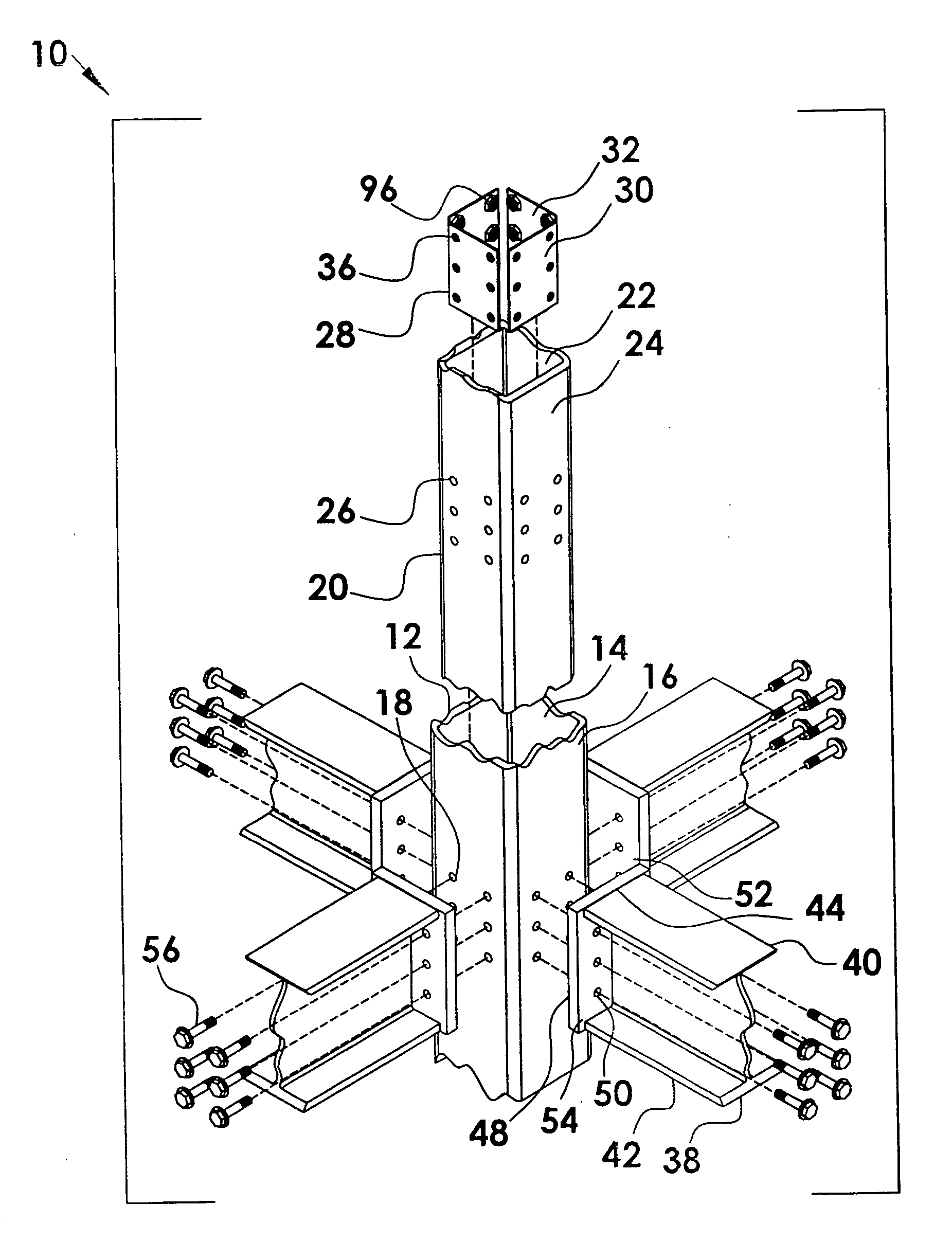
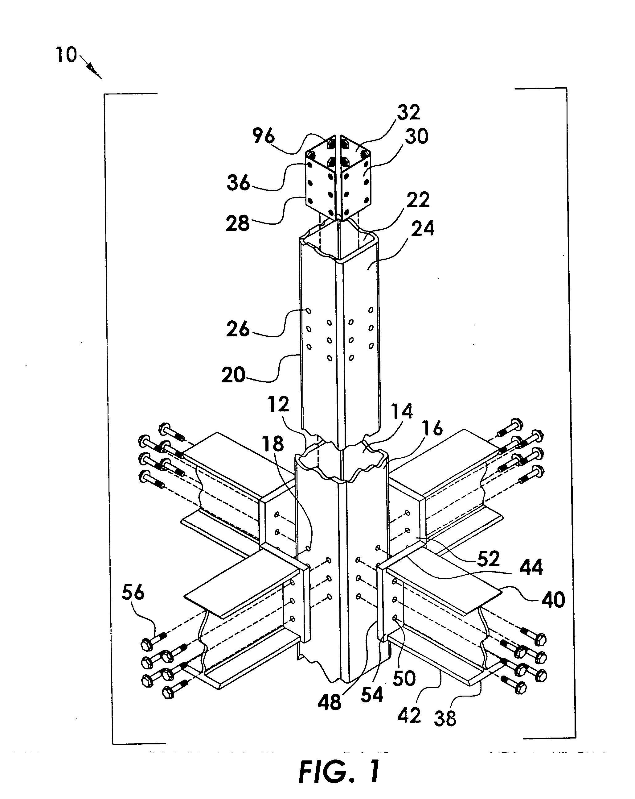
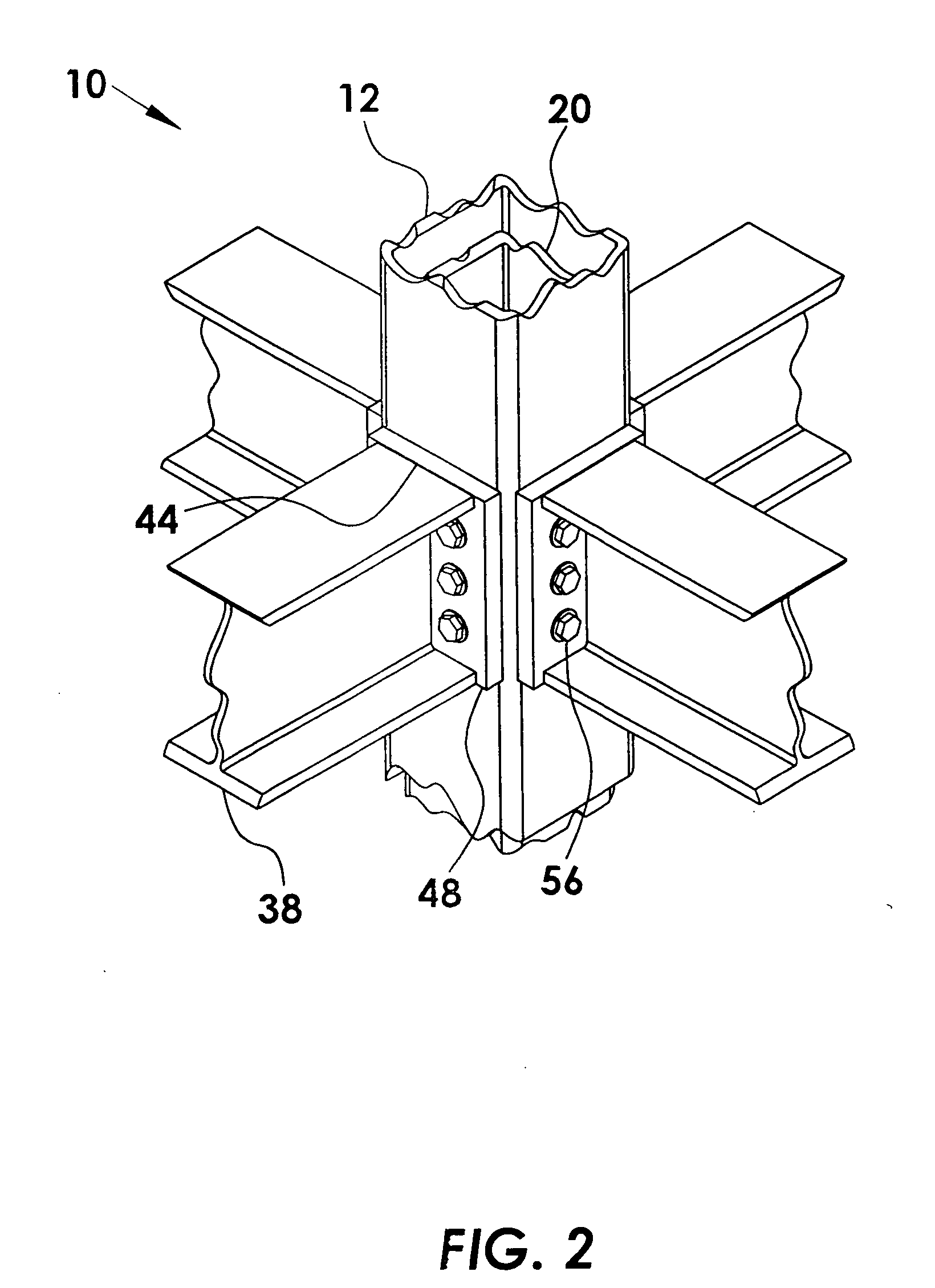
[0036] Described here is a novel moment-resistant building column insert system for distributing lateral and vertical loads between the column-beam and column-foundation connections. The benefits provided by this system are non-welded field connections using bolted connection only. This moment-resistant building column insert system provides strengthening at each level comprising roofs, mid-levels and foundations, where this strengthening is bidirectional and multi-directional.

[0037] Loads are distributed between the building column and beam using a column insert, nut plate assemblies and column plates incorporated to I-beam-ends. The column insert is hollow and of similar cross-section shape to the building column for inserting thereto. The building column, column insert, nut plate assemblies and endplates have patterns of mounting holes for receiving mounting bolts tightened to nuts held by nut plate assemblies. Loads are distributed between the column and foundation using a base...


PUM


Abstract

The invention is a novel moment-resistant building column insert system for distributing lateral and vertical loads between the column-beam and column-foundation connections. Loads are distributed between the column and beam using a column insert, nut plates and beam end plates incorporated to beam-ends. The column insert is hollow and similar cross-section shape to the building column for inserting there to. The column, column insert, nut plates and endplates have patterns of mounting holes for receiving mounting bolts tightened to nuts held by nut plates. Loads are distributed between the column and foundation using a base plate, column insert, and insert plates integrated with anchor bolts, nuts and washers in a concrete foundation. The base plate having mounting holes is incorporated to the building column bottom end to receive the plurality of anchor bolts there through for fixedly tightening as an exposed end of the column insert fits in the column.

Description

FIELD OF INVENTION [0001] The current invention relates to building structure, and in particular a novel moment-resistant building column insert system for distributing lateral and vertical loads between the column-beam and column-foundation connections. [0002] The loads are distributed between the column and beam by interconnecting the beams to columns using a column insert, nut plate assemblies, nuts & bolts, and plates incorporated to the beam ends. The column insert is hollow and generally similar shape to the hollow column inner walls for inserting thereto. The column insert walls are provided with mounting holes for aligning with mounting holes in the building column walls and with mounting holes in the beam endplates for receiving mounting bolts there through and tightening with the nuts held by nut plate assemblies positioned along the inner walls of the column insert. Supplemental beam seats may be added to the column for erection purposes. Supplemental plates may be added ...

Claims


Application Information

Patent Timeline
IPC IPC(8): E04C3/30
CPCE02D27/34E04B1/24E04B2001/2415E04B2001/2418E04B2001/2445E04B2001/2454Y10T403/44E04C3/06E04C3/32E04C2003/0452E04C2003/0465Y10T403/3986Y10T403/34E04B2001/2463F16B9/01F16B9/058
Inventor VAUGHN, WILLIAM B.
Owner VAUGHN WILLAIM B
Why Eureka
Try Eureka