Heat exchanger

Active Publication Date: 2007-09-13
MAHLE INT GMBH
View PDF16 Cites 18 Cited by
  • Summary
  • Abstract
  • Description
  • Claims
  • Application Information

AI Technical Summary

Benefits of technology

[0041] With heat exchanger according to par. 10), the condensation water more easily falls to below the lower tank from the lower end portions of the drain grooves existing in the front and rear opposite side surfaces of the lower tank.
[0042] With the heat exchanger according to par. 11), the first member having tube insertion holes and drain grooves can be made, for example, from a metal blank plate by press work, and is relatively easy to make.
[0043] With the heat exchanger according to par. 12), the condensation water flowing through the drain grooves easily falls to below the lower tank from the lower ends of the grooves. The portions of the front and rear opposite side surfaces of the lower tank where the drain grooves are formed can be positioned forwardly or rearwardly outwardly of the portions therebelow relatively easily, and the lower ends of the drain grooves can be opened at the lower faces of the stepped portions relatively easily.
[0044] With the heat exchanger according to par. 13), recesses are formed between the

Problems solved by technology

Consequently, a relatively great amount of condensation water collects on the top surface of the lower

Method used


Image

  • Heat exchanger
  • Heat exchanger
  • Heat exchanger

Examples


Embodiment Construction

[0056] An embodiments of the present invention will be described below with reference to the drawings. The embodiment is a heat exchanger of the invention for use as an evaporator in motor vehicle air conditioners wherein a chlorofluorocarbon refrigerant is used.

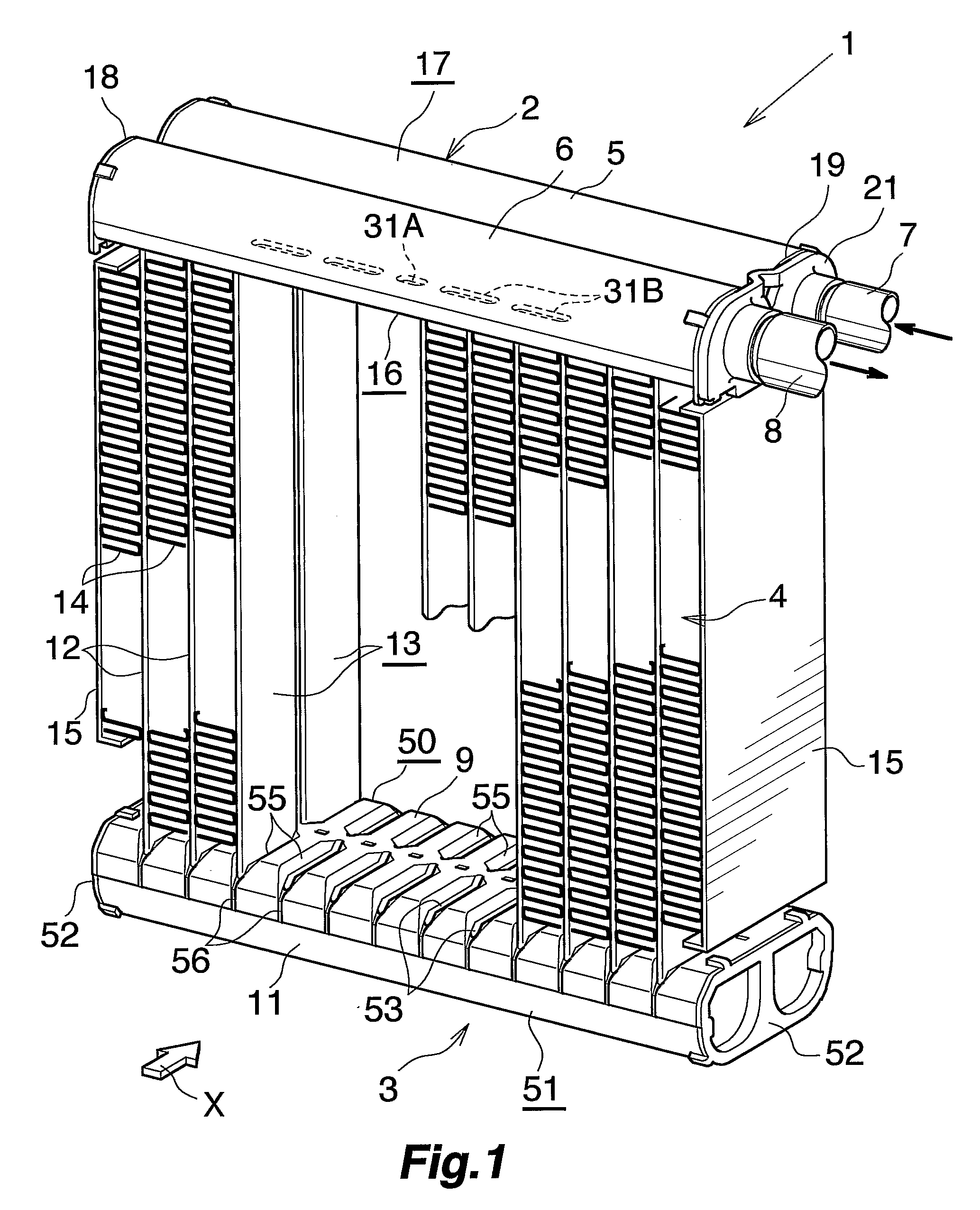
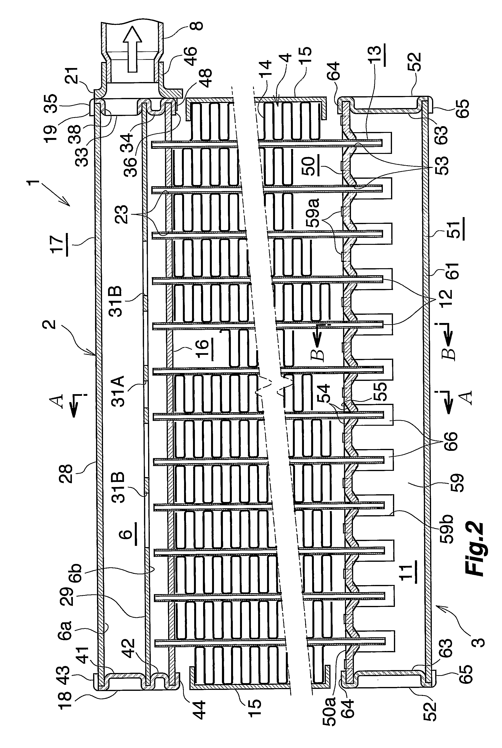
[0057]FIGS. 1 and 2 show the overall construction of a motor vehicle air conditioner evaporator to which the heat exchanger of the invention is applied, FIGS. 3 to 8 show the constructions of main parts, and FIG. 9 shows how the refrigerant flows through the evaporator.

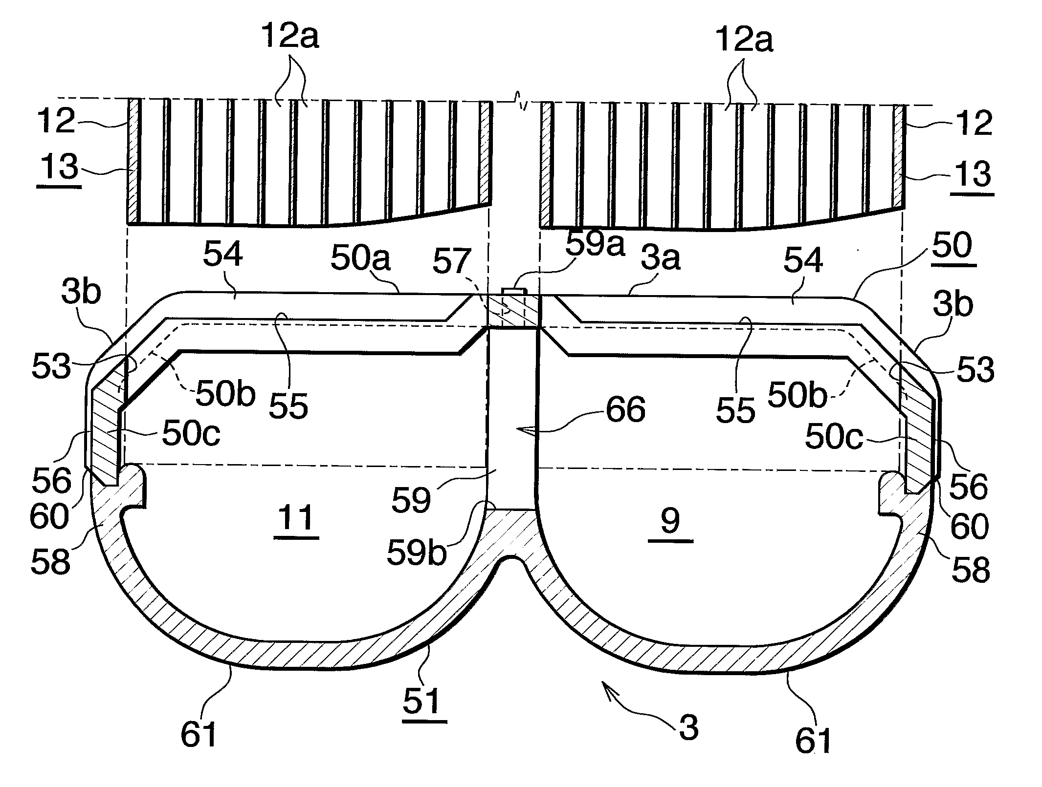
[0058]FIG. 1 and 2 show an evaporator 1 for use in motor vehicle air conditioners wherein a chlorofluorocarbon refrigerant is used. The evaporator 1 comprises a refrigerant inlet-outlet tank 2 of aluminum and a refrigerant turn tank 3 of aluminum (lower tank) which are arranged as vertically spaced apart, and a heat exchange core 4 provided between the two tanks 2, 3.

[0059] The refrigerant inlet-outlet tank 2 comprises a refrigerant inlet header 5 positione...


PUM


Abstract

A heat exchanger for use as an evaporator includes a heat exchange core having a plurality of heat exchange tubes arranged in a left-right direction at a spacing, and a refrigerant turn tank as a lower tank disposed toward a lower end of the heat exchange core. The heat exchange tubes are inserted through respective tube insertion holes formed in the turn tank and joined to the tank, The turn tank has drain grooves each extending from a forwardly or rearwardly outer end of each of the tube insertion holes for discharging condensation water to below the turn tank therethrough. Each of the drain grooves has a bottom extending gradually downward as the bottom extends away from the tube insertion hole. When the exchanger is used as the evaporator, the top surface of the turn tank can be drained of water with an improved efficiency

Description

CROSS REFERENCE TO RELATED APPLICATION [0001] This application is an application filed under 35 U.S.C. §111(a) claiming the benefit pursuant to 35 U.S.C. §119(e)(1) of the filing dates of Provisional Applications No. 60 / 585,835 and No. 60 / 688,353 filed Jul. 8, 2004 and Jun. 8, 2005, respectively, pursuant to 35 U.S.C. §111(b).TECHNICAL FIELD [0002] The present invention relates to heat exchangers suitable to use, for example, as evaporators in motor vehicle air conditioners which are refrigeration cycles for use in motor vehicles. [0003] The downstream side (the direction indicated by the arrow X in FIG. 1, the right-hand side of FIG. 3) of the flow of air to be passed through air passage clearances between respective adjacent pairs of heat exchange tubes of the heat exchanger will be referred to herein and in the appended claims as “front,” and the opposite side as “rear.” Further the upper, lower, left and right sides of the heat exchanger as it is seen from behind toward the fron...

Claims


Application Information

Patent Timeline
IPC IPC(8): F25B39/02
CPCB60H1/00328F25B39/02F25B2309/061F28D1/05391F28F2265/06F28F9/0278F28F17/005F28F2220/00F28F9/0224
Inventor HIGASHIYAMA, NAOHISAWATANABE, SUMITAKAYAMAUCHI, SHINOBU
Owner MAHLE INT GMBH
Why Eureka
Try Eureka