Vehicle Air-Conditioning Related Technique Having Refrigeration Cycle of Supercritical Refrigerant

a technology of supercritical refrigerant and related technology, which is applied in the direction of refrigeration components, machine operation mode, light and heating apparatus, etc., can solve the problems of increasing fuel consumption, increasing power consumption, and reducing mileag

Inactive Publication Date: 2007-09-13
SHOWA DENKO KK
View PDF2 Cites 11 Cited by
  • Summary
  • Abstract
  • Description
  • Claims
  • Application Information

AI Technical Summary

Benefits of technology

[0014] The preferred embodiments of the present invention have been developed in view of the above-mentioned and / or other problems in the related art. The preferred embodiments of the present invention can significantly improve upon existing methods and / or apparatuses.

Problems solved by technology

This ventilation loss may reach about 30% of the overall heat load at the time of the cooling operation, causing additional power consumption, which in turn results in decreased mileage and drastically increased fuel consumption.
Under such technical background, in a refrigeration cycle of carbon-dioxide-gas refrigerant, in cases where discharged air is merely introduced to a heat releasing device as disclosed in the aforementioned patent document, defects, such as variation and / or deviation of introductory air temperature and / or refrigerant temperature, occur, which in turn makes it difficult to obtain stable heat exchange performance.
Consequently, the heat release amount of the refrigerant cannot fully be secured, resulting in inefficient reduction of ventilation loss, which in turn deteriorates energy utilization.

Method used


Image

  • Vehicle Air-Conditioning Related Technique Having Refrigeration Cycle of Supercritical Refrigerant
  • Vehicle Air-Conditioning Related Technique Having Refrigeration Cycle of Supercritical Refrigerant
  • Vehicle Air-Conditioning Related Technique Having Refrigeration Cycle of Supercritical Refrigerant

Examples


Embodiment Construction

[0099] In the following paragraphs, some preferred embodiments of the invention will be described by way of example and not limitation. It should be understood based on this disclosure that various other modifications can be made by those in the art based on these illustrated embodiments.

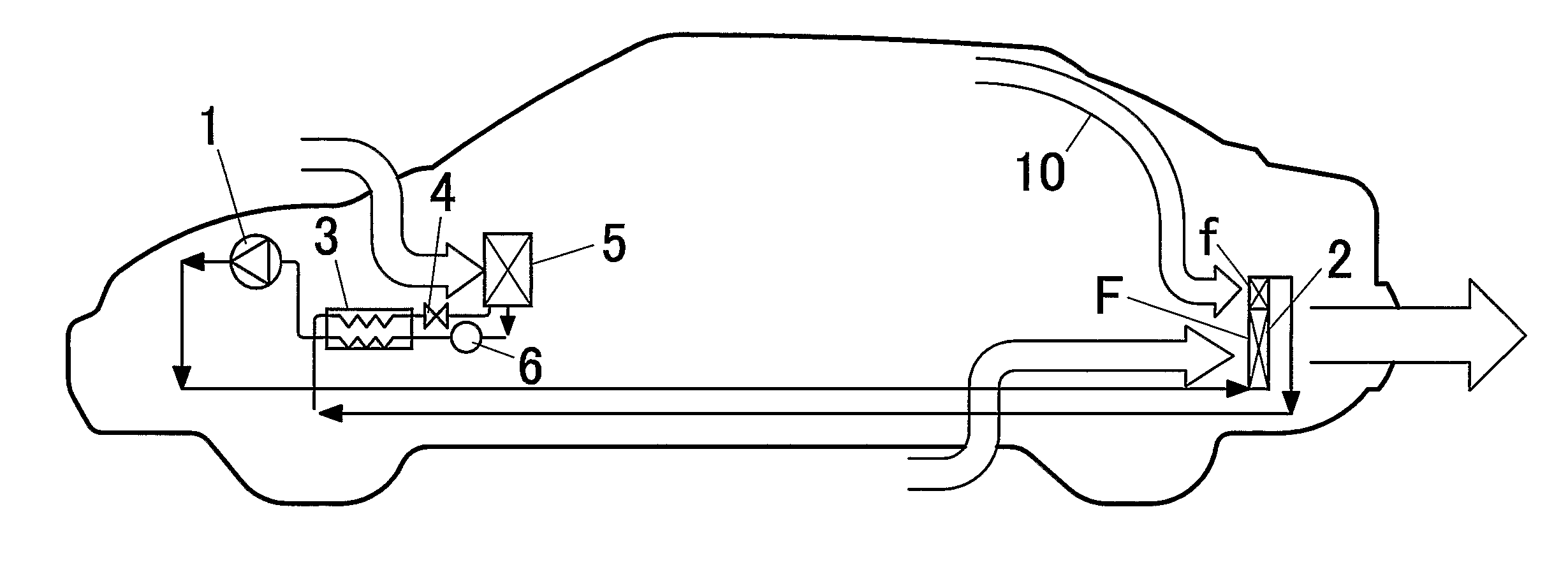
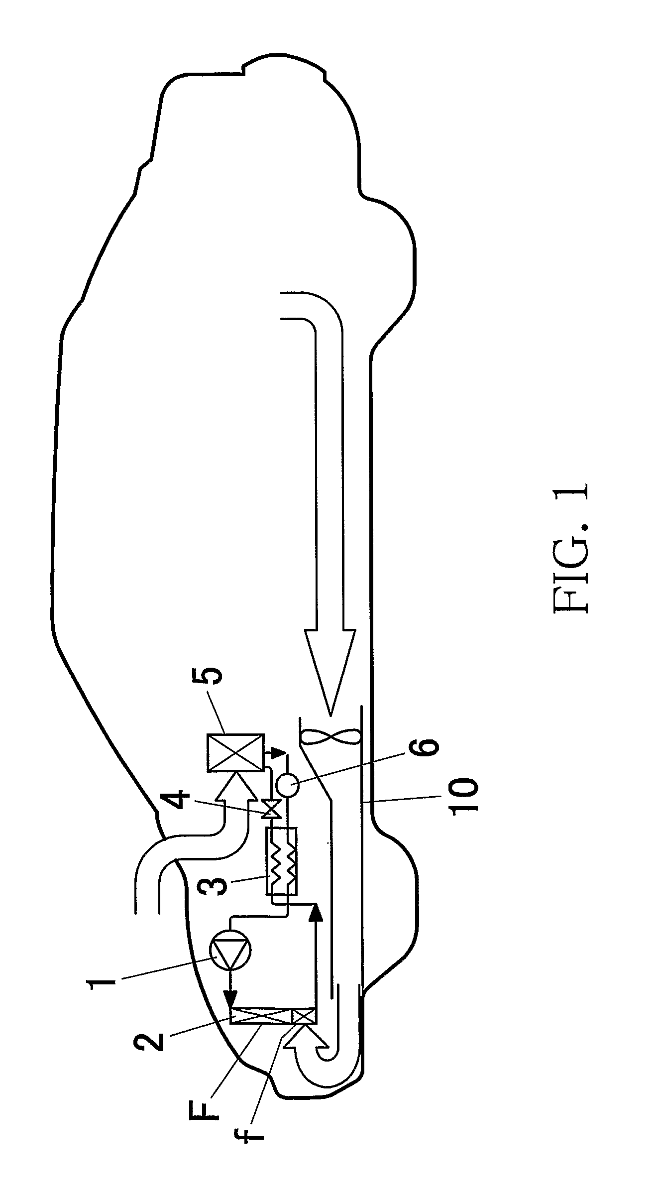
[0100]FIG. 1 is a schematic structural view showing an automobile air-conditioning system employing an air-conditioning apparatus according to an embodiment of the present invention. This refrigeration cycle employed in this automobile utilizes supercritical refrigerant, such as carbon-dioxide-gas (CO2) refrigerant, and includes a compressor 1, a heat releasing device 2, an intermediate heat exchanger 3, an expansion valve 4, an evaporator 5 and an accumulator 6 as shown in FIG. 1.

[0101] In this refrigeration cycle, the refrigerant in a supercritical state compressed by the compressor 1 radiates heat by exchanging heat with refrigerant cooling air, such as ambient air, while passing through the he...


PUM


Abstract

A vehicle air-conditioning apparatus in which supercritical refrigerant passing through a refrigerant heat releasing passage of a heat releasing device exchanges heat with refrigerant cooling air introduced from an air introduction surface of a heat releasing device to be cooled, and the cooled refrigerant exchanges heat with air to be introduced into a passenger compartment by an evaporator. Since at least a part of discharge air discharged from an inside of a passenger compartment is introduced from an air introduction surface of the heat releasing device as a ventilation loss utilizing air, ventilation loss utilizing air can be used as a part of refrigerant cooling air. The ventilation loss utilizing air is introduced to the downstream side area of the refrigerant heat releasing passage in an air introduction surface of the heat releasing device.

Description

[0001] This application claims priority to Japanese Patent Application No. 2003-407379 filed on Dec. 5, 2003 and U.S. Provisional Application No. 60 / 528,496 filed on Dec. 11, 2003, the entire disclosures of which are incorporated herein by reference in their entireties. CROSS REFERENCE TO RELATED APPLICATIONS [0002] This application is an application filed under 35 U.S.C.§111(a) claiming the benefit pursuant to 35 U.S.C.§119(e) (1) of the filing date of U.S. Provisional Application No. 60 / 528,496 filed on Dec. 11, 2003 pursuant to 35 U.S.C §111(b).BACKGROUND OF THE INVENTION [0003] 1. Field of the Invention [0004] The present invention relates to a vehicle air-conditioning related technique having a refrigeration cycle using supercritical refrigerant such as CO2 refrigerant, and more specifically relates to, for example, an air-conditioning apparatus for use in vehicles, an automobile equipped with the apparatus, a heat releasing device for use in vehicle air-conditioning systems an...

Claims


Application Information

Patent Timeline
Patent Type & Authority Applications(United States)
IPC IPC(8): B60H1/03B60H1/00B60H3/00F25B43/00B60HB60H1/24B60H1/32F25B1/00F25B9/00F25B27/02
CPCB60H1/00878B60H1/248B60H1/3227F25B2309/061B60H2001/00957F25B9/008F25B40/00B60H2001/00949B60H1/039
Inventor SHINMURA, ETSUOFURUKAWA, YUICHI
Owner SHOWA DENKO KK
Why Eureka
Try Eureka