Display Support Mechanism

Inactive Publication Date: 2007-09-13
FUNAI ELECTRIC CO LTD
View PDF4 Cites 17 Cited by
  • Summary
  • Abstract
  • Description
  • Claims
  • Application Information

AI Technical Summary

Benefits of technology

[0010] The present invention has been proposed in order to solve the aforementioned problems, and an object of the present invention is to provide a display s

Problems solved by technology

Thus, the operation of controlling the angle of the display screen is disadvantageously complicated.
In the structure employing the round shaft serving as the axis of rotation for inclining the display screen by a prescribed angle as proposed in each of the aforementioned patent documents such as Japanes

Method used


Image

  • Display Support Mechanism
  • Display Support Mechanism
  • Display Support Mechanism

Examples


Example

First Embodiment

[0051] First, the structure of a display support mechanism 1 according to a first embodiment of the present invention is described with reference to FIGS. 1 to 10.

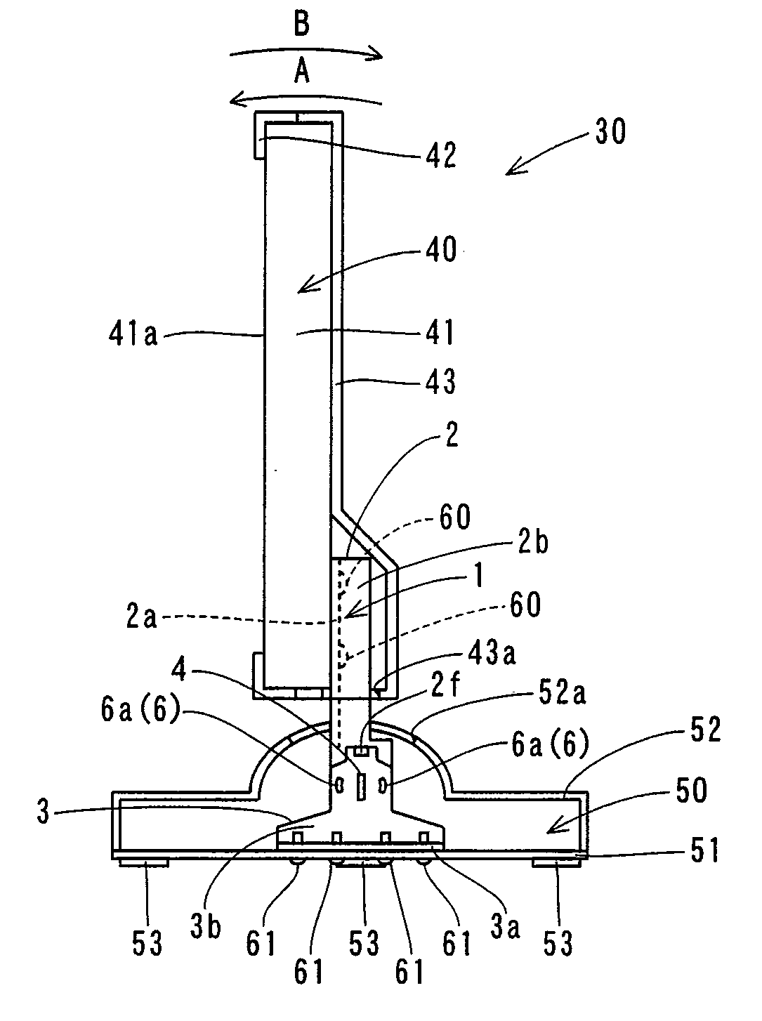
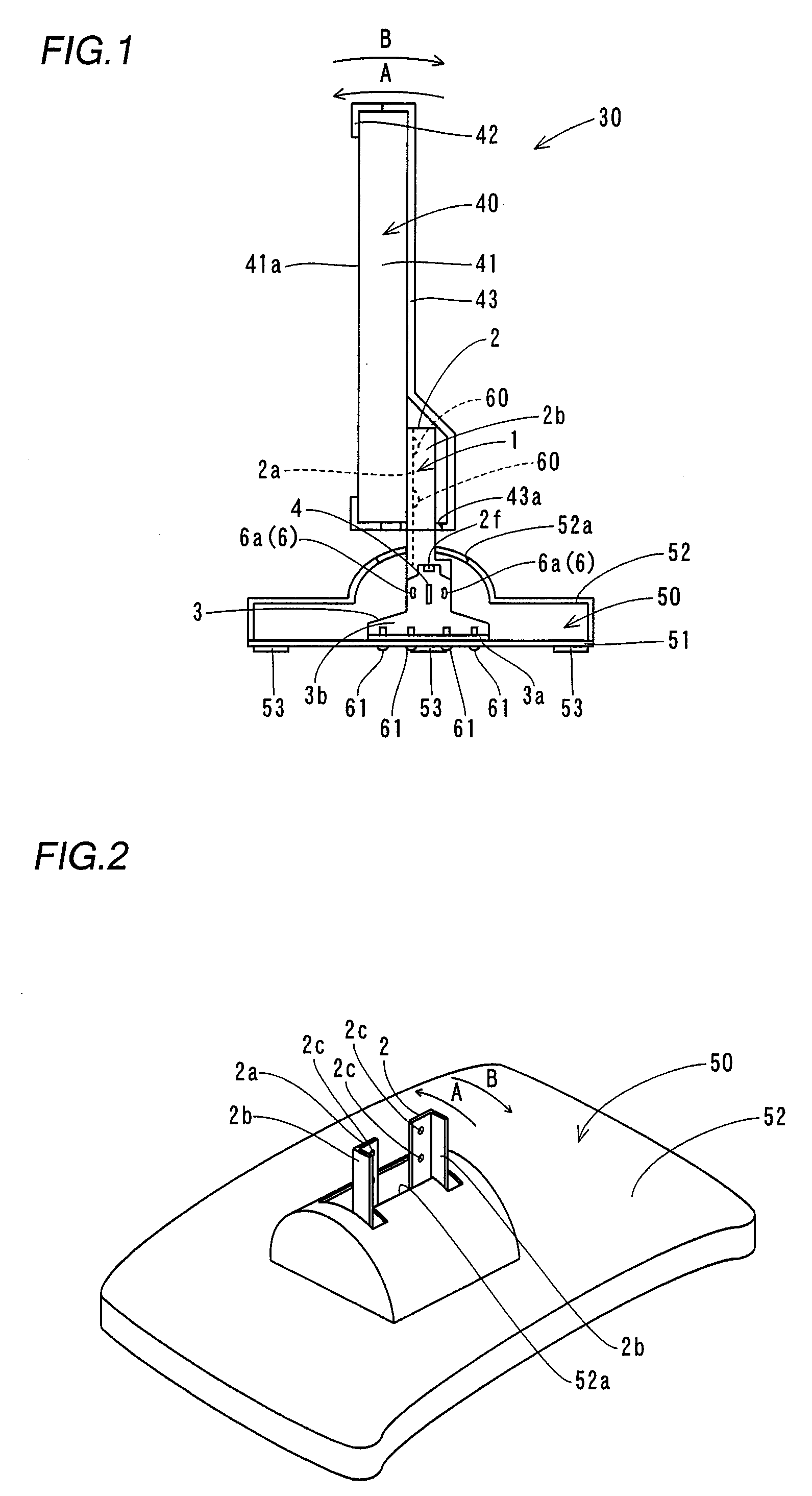
[0052] The display support mechanism 1 according to the first embodiment of the present invention is provided for supporting a liquid crystal display portion 40 of a liquid crystal display 30, as shown in FIG. 1. This display support mechanism 1 is mounted on a base 50. The display support mechanism 1 supports the liquid crystal display portion 40 to be rotatable in directions A and B with respect to the base 50, as shown in FIGS. 1 and 2. The display support mechanism 1 is enabled to support the liquid crystal display portion 40 in a state inclined by a prescribed angle with respect to the base 50. The liquid crystal display portion 40 is an example of the “display screen” in the present invention.

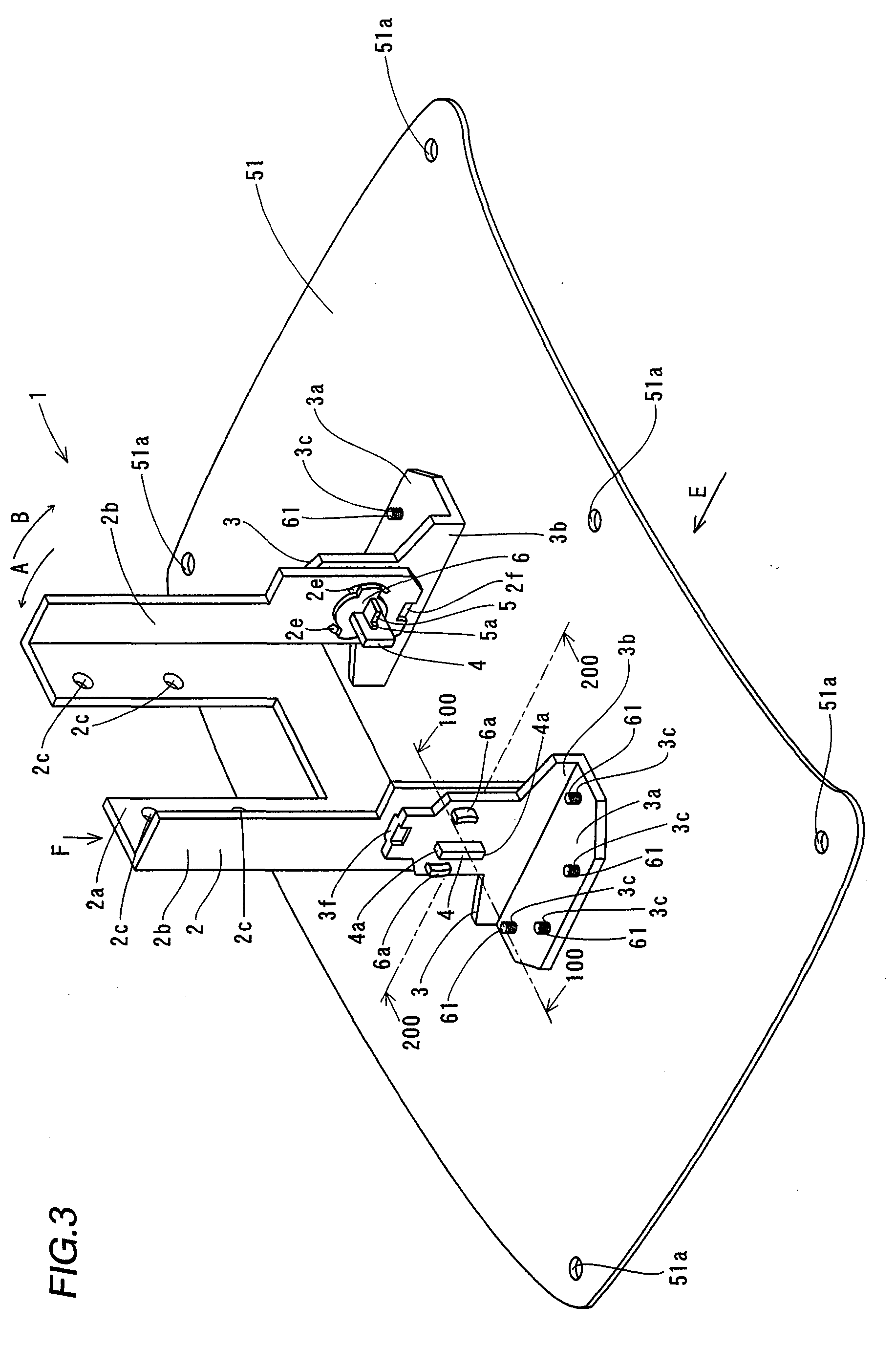
[0053] As shown in FIGS. 3 and 4, the display support mechanism 1 comprises a liquid crystal display portio...

Example

Second Embodiment

[0078] Referring to FIGS. 13 to 16, pressure-contact plates 106 are provided with pairs of projecting portions 106c in a display support mechanism 101 according to a second embodiment of the present invention, dissimilarly to the aforementioned first embodiment. Platelike support shafts 4 and stop members 5 of the display support mechanism 101 according to the second embodiment are similar in structure to those of the aforementioned first embodiment.

[0079] The display support mechanism 101 according to the second embodiment comprises a liquid crystal display portion support member 102, a pair of base support members 103, the platelike support shafts 4 of sheet metal, the stop members 5 of sheet metal and the pressure-contact plates 106 of spring steel, as shown in FIGS. 13 and 14. The liquid crystal display portion support member 102 is an example of the “display screen support member” in the present invention.

[0080] The liquid crystal display portion support mem...


PUM


Abstract

A display support mechanism allowing an easy operation of controlling the angle of a display screen with no requirement for a round shaft serving as an axis of rotation is obtained. This display support mechanism comprises a support shaft provided in the form of a plate, a display screen support member, having a first hole receiving the platelike support shaft, rotatable about the support shaft serving as an axis of rotation and a base support member having a second hole receiving the platelike support shaft, while at least either the display screen support member or the base support member is provided with a projecting portion brought into pressure contact with opposed surfaces of the display screen support member and the base support member for developing frictional resistance.

Description

BACKGROUND OF THE INVENTION [0001] 1. Field of the Invention [0002] The present invention relates to a display support mechanism. [0003] 2. Description of the Background Art [0004] A display support mechanism capable of supporting a display screen in a state inclined by a prescribed angle is known in general, as disclosed in Japanese Utility Model Registration No. 3086465, for example. [0005] The display support mechanism described in Japanese Utility Model Registration No. 3086465 supports the display screen with a pair of support legs, whose angle is varied for controlling the angle of the display screen. The pair of support legs are fixed by pins, for fixing the angle of the display screen. [0006] In the display support mechanism described in the aforementioned Japanese Utility Model Registration No. 3086465, however, the pins fixing the support legs must be loosened in order to control the angle of the display screen, and thereafter refastened for refixing the support legs. Thus...

Claims


Application Information

Patent Timeline
IPC IPC(8): F16M11/00
CPCF16M2200/08F16M11/10Y10S248/917Y10S248/919
Inventor SAWAI, KUNIOYOKOTA, KATSUYUKI
Owner FUNAI ELECTRIC CO LTD
Why Eureka
Try Eureka