Gas-liquid mixing distribution system

A distribution system, gas-liquid mixing technology, applied in the direction of hydrocarbon oil cracking, hydrocarbon oil treatment, chemical instruments and methods, etc., can solve the problems of low heat transfer efficiency, uneven mass transfer and heat transfer, and difficulty in uniform distribution, etc., to achieve improved Heat transfer efficiency, saving investment, uniform distribution effect

Pending Publication Date: 2020-08-21
CHINA PETROLEUM & CHEM CORP +2
View PDF12 Cites 0 Cited by
  • Summary
  • Abstract
  • Description
  • Claims
  • Application Information

AI Technical Summary

Problems solved by technology

[0010] In order to solve the technical problems existing in the prior art that the gas-liquid two-phase fluid is difficult to distribute evenly in the catalyst bed,

Method used


Image

  • Gas-liquid mixing distribution system
  • Gas-liquid mixing distribution system
  • Gas-liquid mixing distribution system

Examples


Example Embodiment

[0034] The present invention will be further described below in conjunction with the drawings.

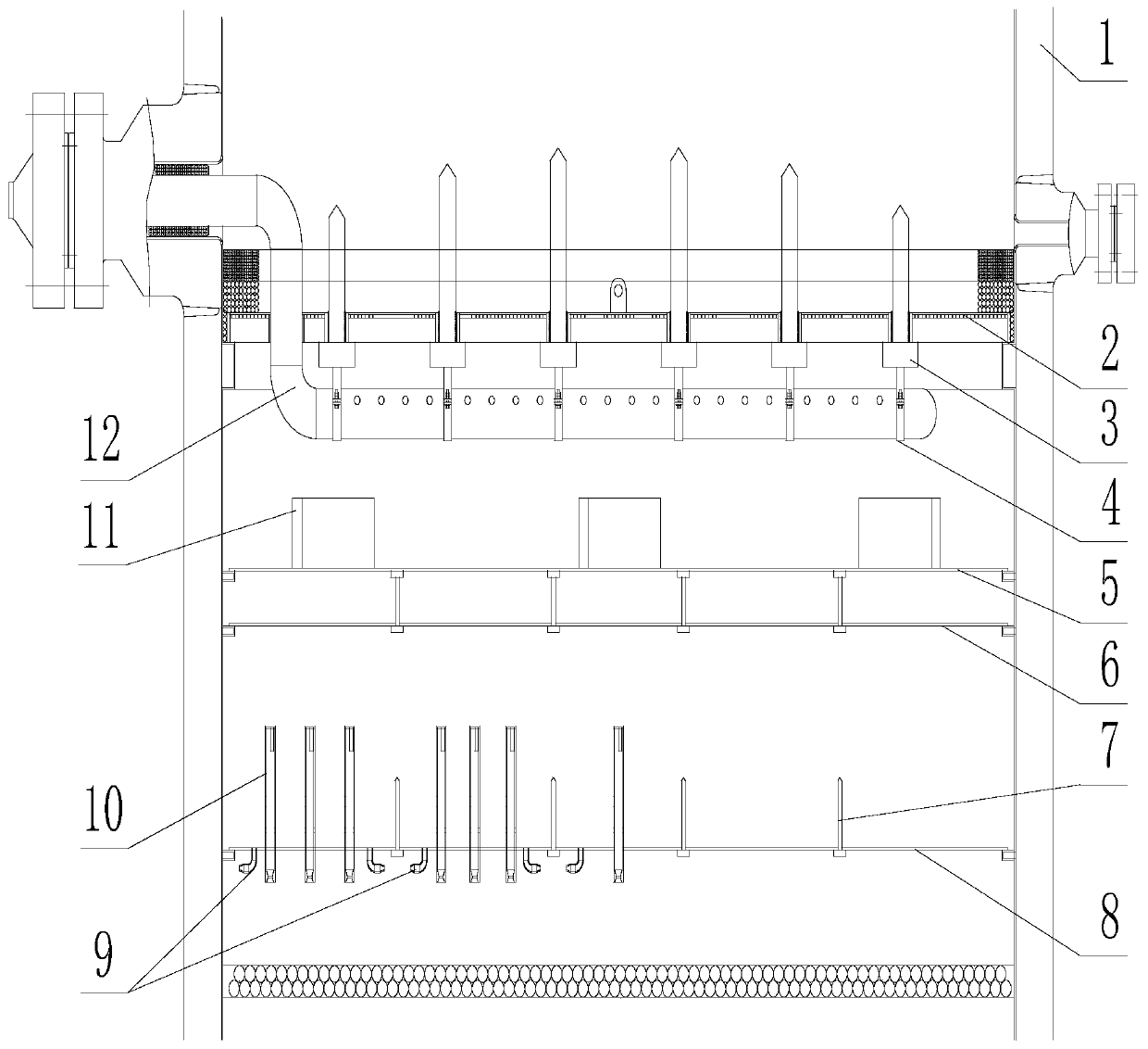
[0035] Such as figure 1 As shown, the gas-liquid mixing distribution system of the present invention includes a casing 1, a catalyst grid 2 fixed on the inner wall of the casing 1 and a catalyst grid support beam 3, and a cold hydrogen distributor support located below the catalyst grid 2 The cold hydrogen distributor 12 on the beam 4, the mixing chamber 11 located below the cold hydrogen distributor 12 and fixed on the collecting plate 5, the coarse distribution plate 6 located under the collecting plate 5, and the coarse distribution plate 6 located under the coarse distribution plate 6 and fixed to the distributor The gas-liquid distributor 10 on the disk 8; the distribution disk 8 is fixedly connected with the distribution disk support beam 7 and the inner wall of the housing 1 respectively, and the distribution disk 8 is located on both sides of the distribution disk support beam ...


PUM


Abstract

The invention discloses a gas-liquid mixing distribution system. The system comprises a shell, and a catalyst grid, a cold hydrogen distributor, a collecting disc, a gas-liquid distributor and a distribution disc which are arranged in the shell from top to bottom; mixing chambers are uniformly arranged on the collecting disc; and the distribution disc is fixedly connected with distribution disc supporting beams and the inner wall of the shell respectively, the gas-liquid distributor is vertically fixed on the distribution disc, gas-liquid spray heads are arranged at the positions, located onthe two sides of the distribution disc supporting beams and the inner wall of the shell, of the distribution disc, the gas-liquid spray heads on the two sides of the distribution disc supporting beamsare oppositely arranged in a staggered mode or obliquely arranged in pairs, and the gas-liquid spray heads on the inner wall of the shell are arranged right opposite to the inner wall of the shell orobliquely opposite to the inner wall of the shell. Cold hydrogen can be more uniformly distributed on the total cross section of a reactor, dead zones on the inner wall of the shell and the distribution disc supporting beams are reduced, and the uniform distribution of gas and liquid on the total cross section of the reactor is fully guaranteed.

Description

technical field [0001] The invention belongs to the field of petroleum processing, and in particular relates to a gas-liquid mixing distribution system. Background technique [0002] Due to the exothermic reaction of gas, liquid and solid in the hydrogenation process, in order to make the reaction feed (gas and liquid two phases) and the catalyst (solid phase) fully, uniformly and effectively contact, the hydrogenation reactor is generally designed There are multiple catalyst beds, a distribution plate is set on the top of each bed, and a temperature control structure (cold hydrogen box) is installed between the two beds to ensure the safe and stable production and extension of the hydrogenation unit Catalyst service life. [0003] The hydrogenation reaction of hydrocarbons is an exothermic reaction. For a multi-bed hydrogenation reactor, the temperature of oil gas and hydrogen will rise after the reaction of the upper bed layer. In order to continue the effective reaction ...

Claims


Application Information

Patent Timeline
IPC IPC(8): B01J8/04C10G45/00C10G47/00C10G49/00
CPCB01J8/04B01J8/0278B01J8/0285B01J8/0292C10G45/00C10G47/00C10G49/00
Inventor 李双权曾茜李群生张光黎张国信晁君瑞
Owner CHINA PETROLEUM & CHEM CORP
Why Eureka
Try Eureka