RFID Smart Label with Reduced Layers and Method of Production

Inactive Publication Date: 2007-09-13
WAVEZERO
View PDF3 Cites 35 Cited by
  • Summary
  • Abstract
  • Description
  • Claims
  • Application Information

AI Technical Summary

Benefits of technology

[0010]The present invention provides a method for reliably and economically forming antenna patterns used for RFID tags using semiconductor-like processes or simp

Problems solved by technology

While the cost of assembling a modern RFID smart label is arguably small because of the economies of high speed printing and label converting devices, the cost is still more than the majority of significant users can afford.
Although specialized high end markets are willing to pay more for RFID smart labels, the broader and larger commercial (consumer) market for RFID smart labels is not expected to emerge until the price of an RFID smart label approaches $0.05 (or lower).
This approach is relatively cumbersome and too expensive for the rapidly expanding markets of RFID smart labels.
One problem with making reliable

Method used


Image

  • RFID Smart Label with Reduced Layers and Method of Production
  • RFID Smart Label with Reduced Layers and Method of Production
  • RFID Smart Label with Reduced Layers and Method of Production

Examples


Embodiment Construction

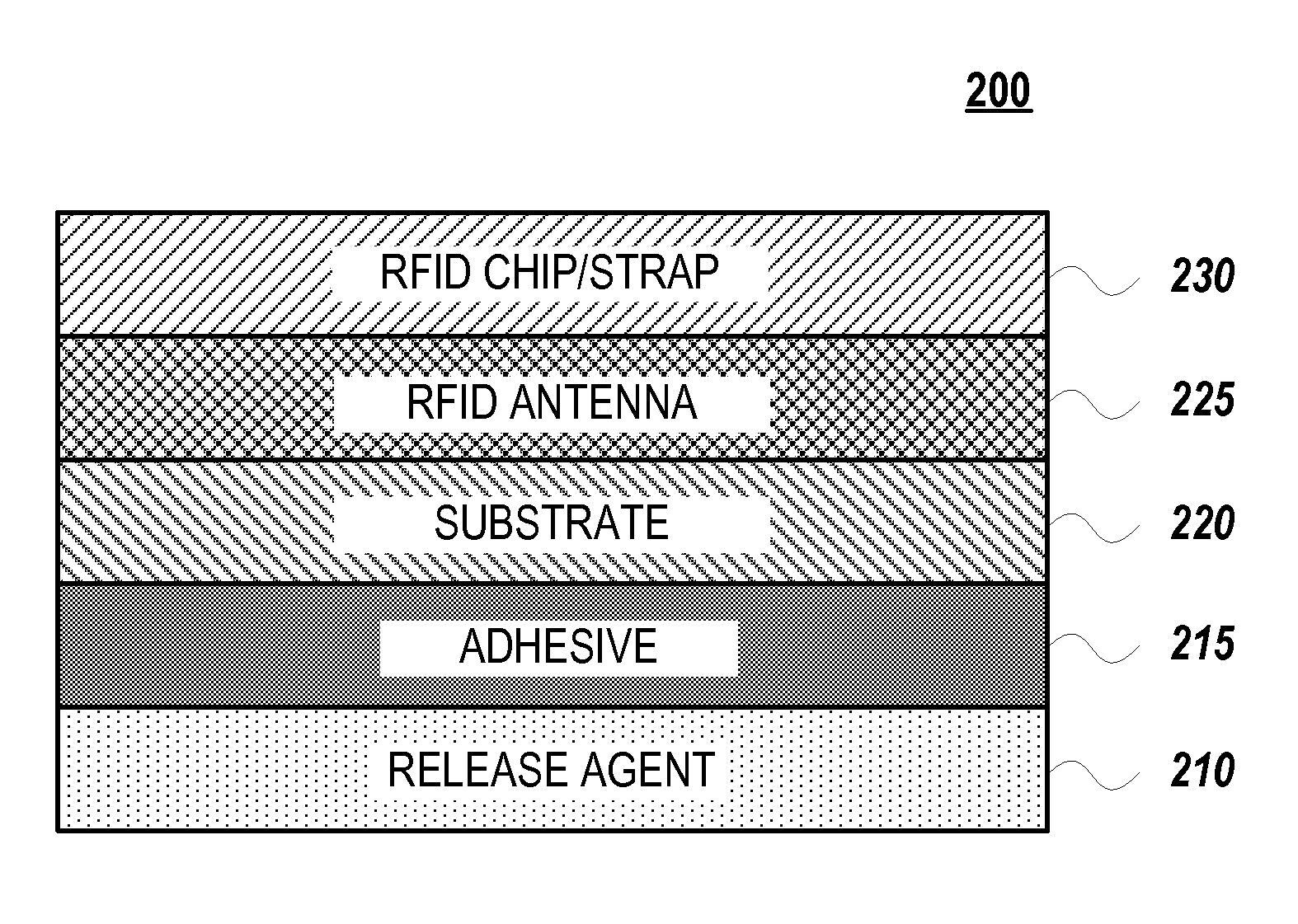
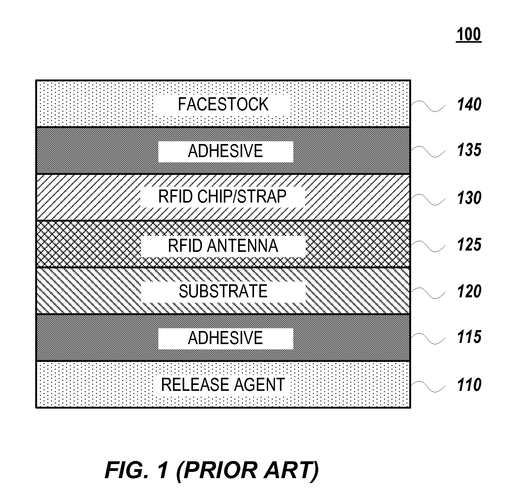
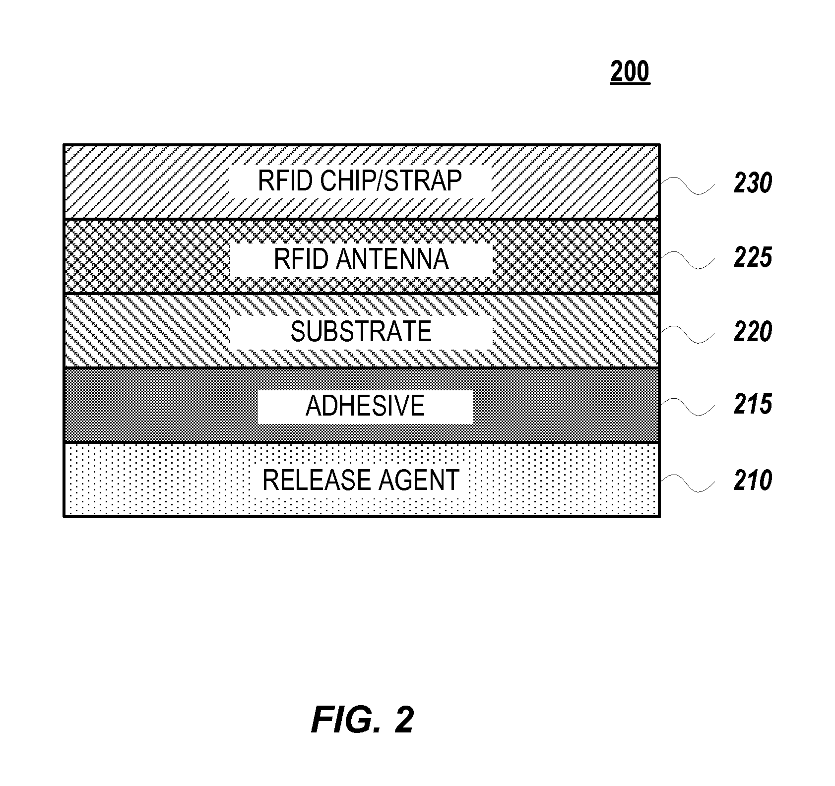
[0049]Embodiments of the present invention include RFID smart tags and labels with fewer layers that can be manufactured using roll to roll processing. Embodiments of the present invention also include methods for making RFID smart tags and labels having fewer layers. RFID smart tags and labels include layered structures where the facestock and facestock adhesive layers illustrated in FIG. 1 have been removed and a depression / recession region is provided to make room for the RFIC or RFID chip / strap. The RFID chip / strap is positioned within the depression / recession region so that graphics or information normally contained on the facestock can be printed directly onto the RFID chip / strap. Methods for making both conventional RFID tags and RFID smart tags and labels, in accordance with embodiments of the invention, include first impressing a pattern on a surface of a substrate to make a first portion of the substrate have a positive image of the RFID antenna and a second portion of the...


PUM


Abstract

An RFID smart label includes a plurality of layers, wherein one of the plurality of layers is an RFID inlay with a depression/recession region for holding the RFID chip/strap so that it does not extend above the surface of the antenna. The depressed/recessed region can have substantially the same depth as the thickness of the RFID chip/strap. High speed printing processes are then used to economically print labels on the RFID inlays having the RFID chip/strap embedded because there are no bumps to impede the printing process. A method for reliably and economically manufacturing a radiofrequency identification (RFID) antenna includes impressing a pattern on a surface of a substrate to make a first portion of the substrate having a positive image of the RFID antenna and a second portion of the substrate having a negative image of the RFID antenna, applying a release agent on the second portion of the substrate having a negative image of the RFID antenna, depositing a metallization layer over the surface of the substrate, applying a solvent over the metallization layer, and scraping the surface of the substrate causing mechanical interruption of the metallization layer. The release agent can be masking materials containing TiO2 or oil.

Description

CROSS-REFERENCES TO RELATED APPLICATIONS[0001]This application claims the benefit of U.S. Provisional Application No. 60 / 781,114, filed Mar. 10, 2006, and U.S. Provisional Application No. 60 / 852,373, filed Oct. 16, 2006, which are incorporated herein by reference in their entirety for all purposes.BACKGROUND OF THE INVENTION[0002]The present invention relates generally to radio frequency identification (RFID) tags and in particular to the design and manufacture of RFID straps and inlays fabricated out of planar roll materials (paper, polymer, etc.) in a manner that causes the RFID chip / strap to be at or below the surfaces of the planar material.[0003]RFID is an emerging technology for identifying many manners of assets including people, equipment, products etc based upon radio communications. RFID has been viewed as a replacement technology for bar codes. An RFID tag is a complete device designed to receive a radio frequency communication at a specific frequency and return a radio f...

Claims


Application Information

Patent Timeline
IPC IPC(8): G08B13/14
CPCB31D1/021G06K19/07749G06K19/07722B31D1/028
Inventor ARNOLD, ROCKY R.ANTONIUCCI, PIER GIORGIO
Owner WAVEZERO
Why Eureka
Try Eureka