Beamforming RF circuit and applications thereof

a beamforming and circuit technology, applied in the field of wireless communication systems, can solve the problems of further adding to the complexity and component count of the beamforming transmitter

Inactive Publication Date: 2007-09-13
AVAGO TECH INT SALES PTE LTD
View PDF13 Cites 258 Cited by
  • Summary
  • Abstract
  • Description
  • Claims
  • Application Information

AI Technical Summary

Problems solved by technology

Note that gain adjust modules may be added in series with the phase modules, but further adds to the complexity and component count of the beamforming transmitter.

Method used


Image

  • Beamforming RF circuit and applications thereof
  • Beamforming RF circuit and applications thereof
  • Beamforming RF circuit and applications thereof

Examples


Embodiment Construction

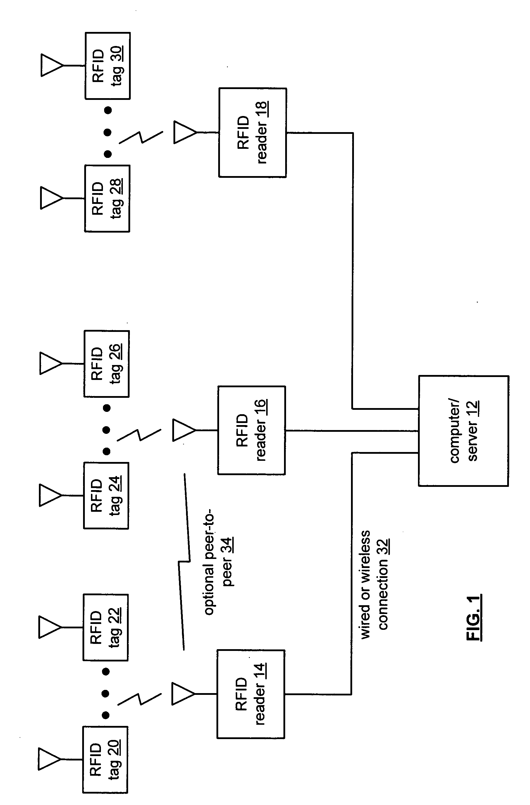
[0029]FIG. 1 is a schematic block diagram of an RFID (radio frequency identification) system that includes a computer / server 12, a plurality of RFID readers 14-18 and a plurality of RFID tags 20-30. The RFID tags 20-30 may each be associated with a particular object for a variety of purposes including, but not limited to, tracking inventory, tracking status, location determination, assembly progress, et cetera.

[0030] Each RFID reader 14-18 wirelessly communicates with one or more RFID tags 20-30 within its coverage area. For example, RFID reader 14 may have RFID tags 20 and 22 within its coverage area, while RFID reader 16 has RFID tags 24 and 26, and RFID reader 18 has RFID tags 28 and 30 within its coverage area. The RF communication scheme between the RFID readers 14-18 and RFID tags 20-30 may be a back scatter technique whereby the RFID readers 14-18 provide energy to the RFID tags via an RF signal. The RFID tags derive power from the RF signal and respond on the same RF carrie...


PUM


Abstract

A beamforming radio frequency (RF) circuit includes a plurality of antennas, a plurality of amplifiers and an adjust module. The plurality of antennas is operably coupled to interrelate a plurality of beamformed signal components with a beamformed signal. The plurality of amplifiers is operably coupled to interrelate the plurality of beamformed signal components with a plurality of adjusted signal components. The adjust module is operably coupled to interrelate coordinates of a signal with the plurality of adjusted signal components.

Description

CROSS REFERENCE TO RELATED PATENTS [0001] Not Applicable STATEMENT REGARDING FEDERALLY SPONSORED RESEARCH OR DEVELOPMENT [0002] Not Applicable INCORPORATION-BY-REFERENCE OF MATERIAL SUBMITTED ON A COMPACT DISC [0003] Not Applicable BACKGROUND OF THE INVENTION [0004] 1. Technical Field of the Invention [0005] This invention relates generally to wireless communication systems and more particularly to beamforming. [0006] 2. Description of Related Art [0007] Communication systems are known to support wireless and wire lined communications between wireless and / or wire lined communication devices. Such communication systems range from national and / or international cellular telephone systems to the Internet to point-to-point in-home wireless networks to radio frequency identification (RFID) systems. Each type of communication system is constructed, and hence operates, in accordance with one or more communication standards. For instance, wireless communication systems may operate in accorda...

Claims


Application Information

Patent Timeline
Patent Type & Authority Applications(United States)
IPC IPC(8): H01Q3/00
CPCH01Q3/26
Inventor ROFOUGARAN AHMADREZA
Owner AVAGO TECH INT SALES PTE LTD
Why Eureka
Try Eureka