
Eye state sensor

a technology of eye state and sensor, applied in the field of eye state sensor, can solve problems such as particular problems of ocular intervention

Inactive Publication Date: 2007-09-13
PHARMACIA CORP
View PDF16 Cites 45 Cited by
  • Summary
  • Abstract
  • Description
  • Claims
  • Application Information

AI Technical Summary

Benefits of technology

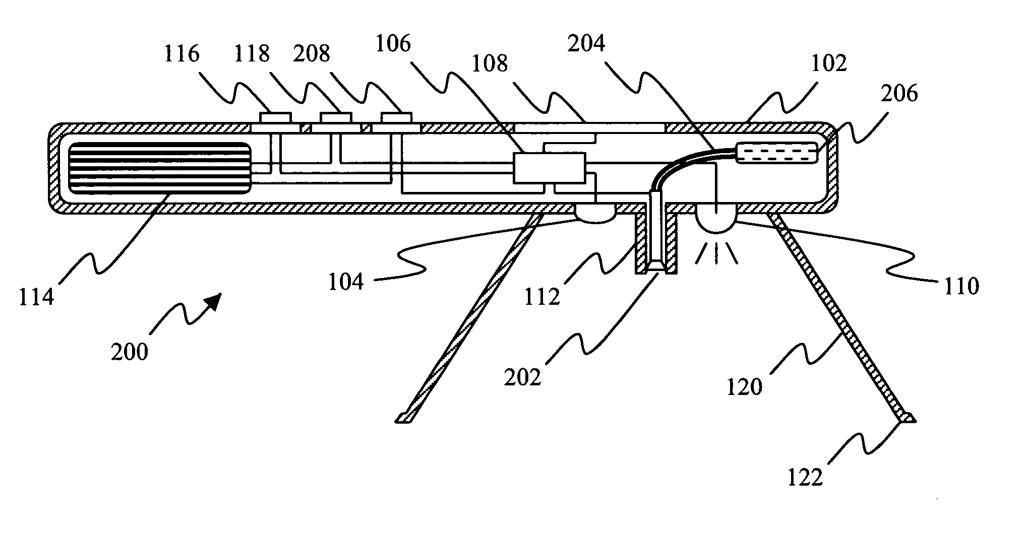
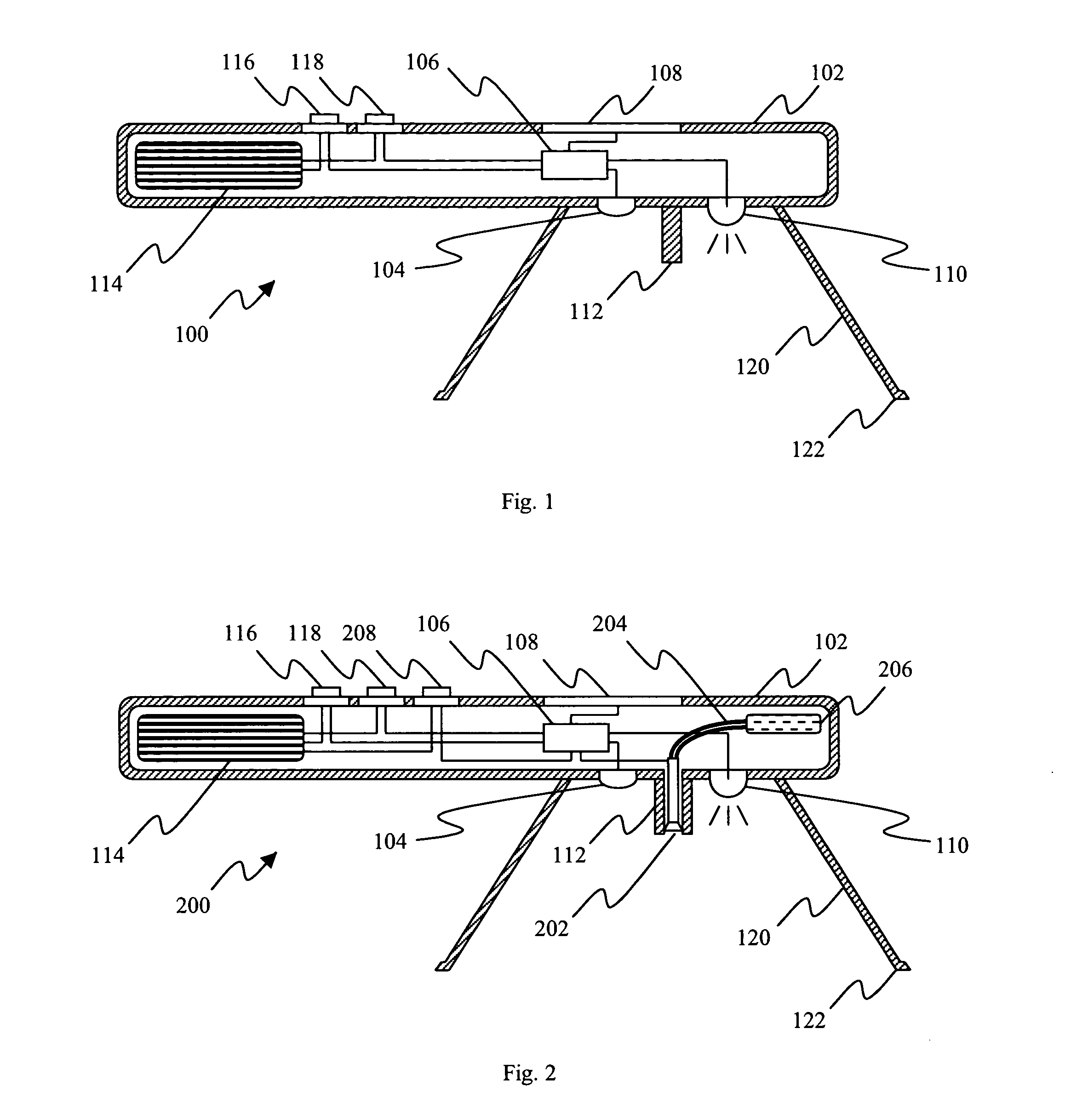
[0010] Further provided is an apparatus for treating an eye of a subject. This apparatus comprises a device for sensing the state of an eye as described above, an applicator for delivering a substance to the ey

Problems solved by technology

The voluntary or involuntary act of blinking, i.e., rapidly closing and opening the eye, presents particular problems for ocular intervention.
Moreover, the very act of ocular intervention, for example delivering a substance to the eye, can provoke an involuntary blink response, resulting in all or part of the substance intended for delivery to the eye itself being deposited instead on the outer surface of an eyelid or being caught by eyelashes.

Method used


Image

  • Eye state sensor
  • Eye state sensor
  • Eye state sensor

Examples


example 1

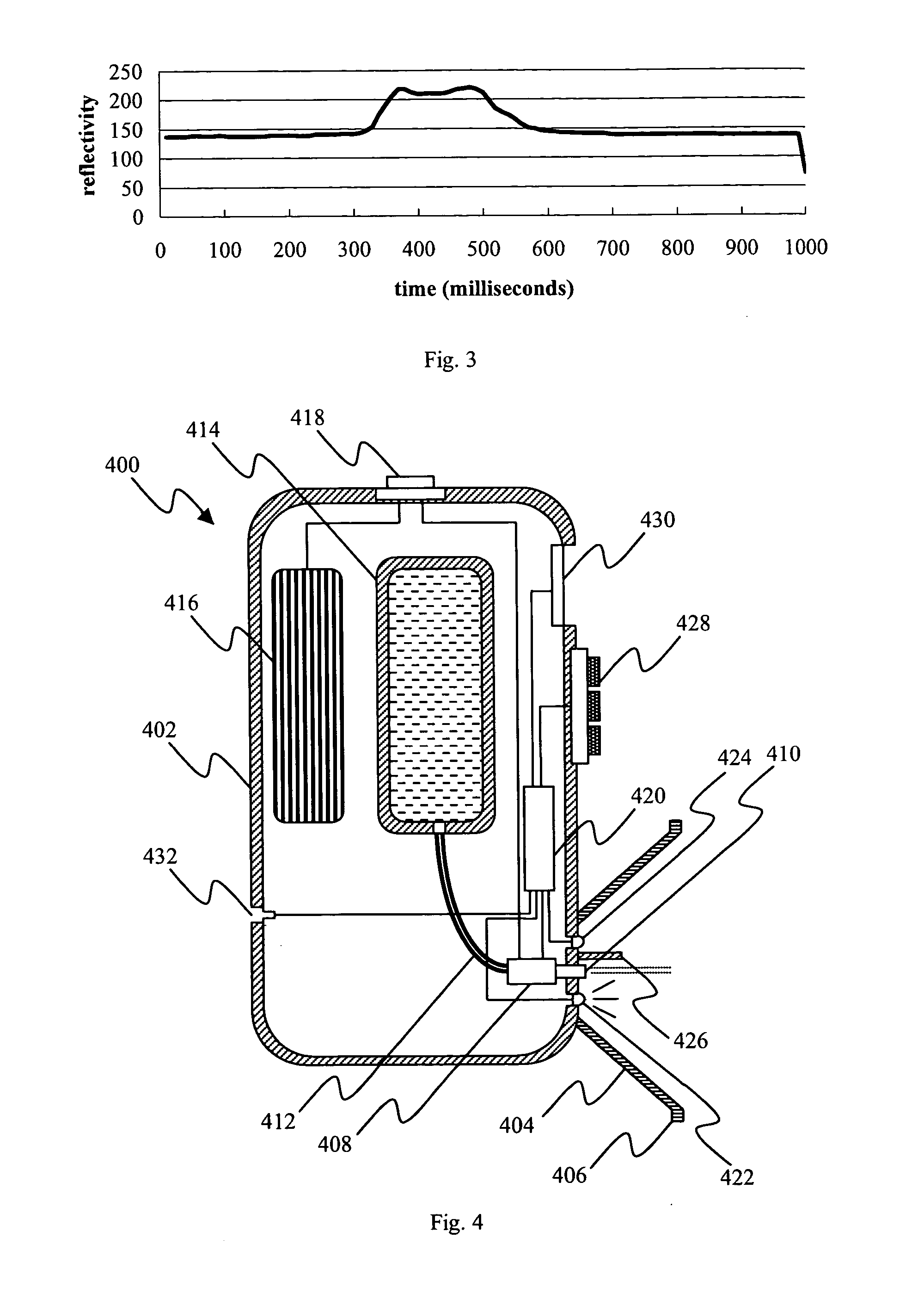
[0065] A computer controlled test apparatus was constructed. The test apparatus comprised a light source in the form of an LED capable of directing light toward a subject's eye and a sensor in the form of a receiver diode capable of receiving light reflected from the eye, and was controlled and powered by a microcontroller connected to a personal computer (PC).

[0066] Luminance of light from the LED reflected from an ocular surface was received by the sensor and converted into a voltage. The voltage provided an analog signal that was filtered to reduce background noise and passed through an amplifier before being routed to an analog / digital (A / D) converter in the microcontroller. The A / D converter transformed the voltage into a discrete numerical value between 0 and 255. This value was routed to the PC and displayed on the PC screen. To allow for calibration of the apparatus, five resistors in the amplifier were controlled via the microcontroller such that, by selectively actuating ...

example 2

[0070] The apparatus of Example 1 having a red LED and visible light sensor, and the apparatus of Example 1 having an infrared LED and infrared sensor, were tested on the same 8 subjects as in Example 1. Measurements of reflectivity of open and closed eyes were made for each of the eight individuals on three successive days using both versions of the apparatus. Results with red light are presented in Table 1 and with infrared light in Table 2.

TABLE 1Reflectivity with red light (scaled numerical value)SubjectEye colorEye stateDay 1Day 2Day 31brownopen91981021brownclosed1351481202brownopen4051422brownclosed5575683greenopen7075683greenclosed1551821574greenopen9284984greenclosed1451221405blueopen78100925blueclosed118113996blueopen6062526blueclosed8590707grayopen7074677grayclosed1041101028grayopen7277728grayclosed879087

[0071]

TABLE 2Reflectivity with infrared light (scaled numerical value)SubjectEye colorEye stateDay 1Day 2Day 31brownopen1702001701brownclosed2052152102brownopen113118115...


PUM


Abstract

A method for sensing the state of an eye of a subject comprises measuring light reflected from an ocular surface and comparing the measured light to a reference. A method for treating an eye of a subject comprises sensing the state of the eye as described above, and controlling whether a substance is delivered to the eye whereby the substance is so delivered only when the eye is sensed to be open. A device for sensing the state of an eye comprises a light source that directs light to an ocular surface of a subject, and a sensor for measuring light reflected from the ocular surface. An apparatus for treating an eye of a subject comprises a device for sensing the state of an eye as described above, an applicator for delivering a substance to the eye, and a control system that permits delivery of the substance when the sensing device detects that the eye is open but prevents delivery of the substance when the sensing device detects that the eye is closed.

Description

[0001] This application claims priority of U.S. provisional application Ser. No. 60 / 413,928 filed on Sep. 26, 2002.FIELD OF THE INVENTION [0002] The present invention relates to a method and apparatus for detecting the state of an eye, i.e., whether the eye is open or closed. In particular, the invention relates to a method and apparatus for controlling timing of ocular intervention required in diagnosis, prevention or treatment of an ophthalmic condition, disorder or disease. BACKGROUND OF THE INVENTION [0003] In ophthalmic medicine it is frequently desired to administer substances directly to, or otherwise treat, an open eye. Success in such administration or treatment, herein generically referred to as ocular intervention, frequently relies upon ensuring that the eye does not close during or at the moment of intervention. [0004] The voluntary or involuntary act of blinking, i.e., rapidly closing and opening the eye, presents particular problems for ocular intervention. The normal...

Claims


Application Information

Patent Timeline
IPC IPC(8): A61B3/10A61B3/113A61F9/00
CPCA61B3/0008A61F9/0008A61B3/113A61P27/06
Inventor BENNWIK, PERCY
Owner PHARMACIA CORP
Learn More