Optical disc apparatus, tracking control method, and integrated circuit
- Summary
- Abstract
- Description
- Claims
- Application Information
AI Technical Summary
Benefits of technology
Problems solved by technology
Method used
Image
Examples
embodiment 1
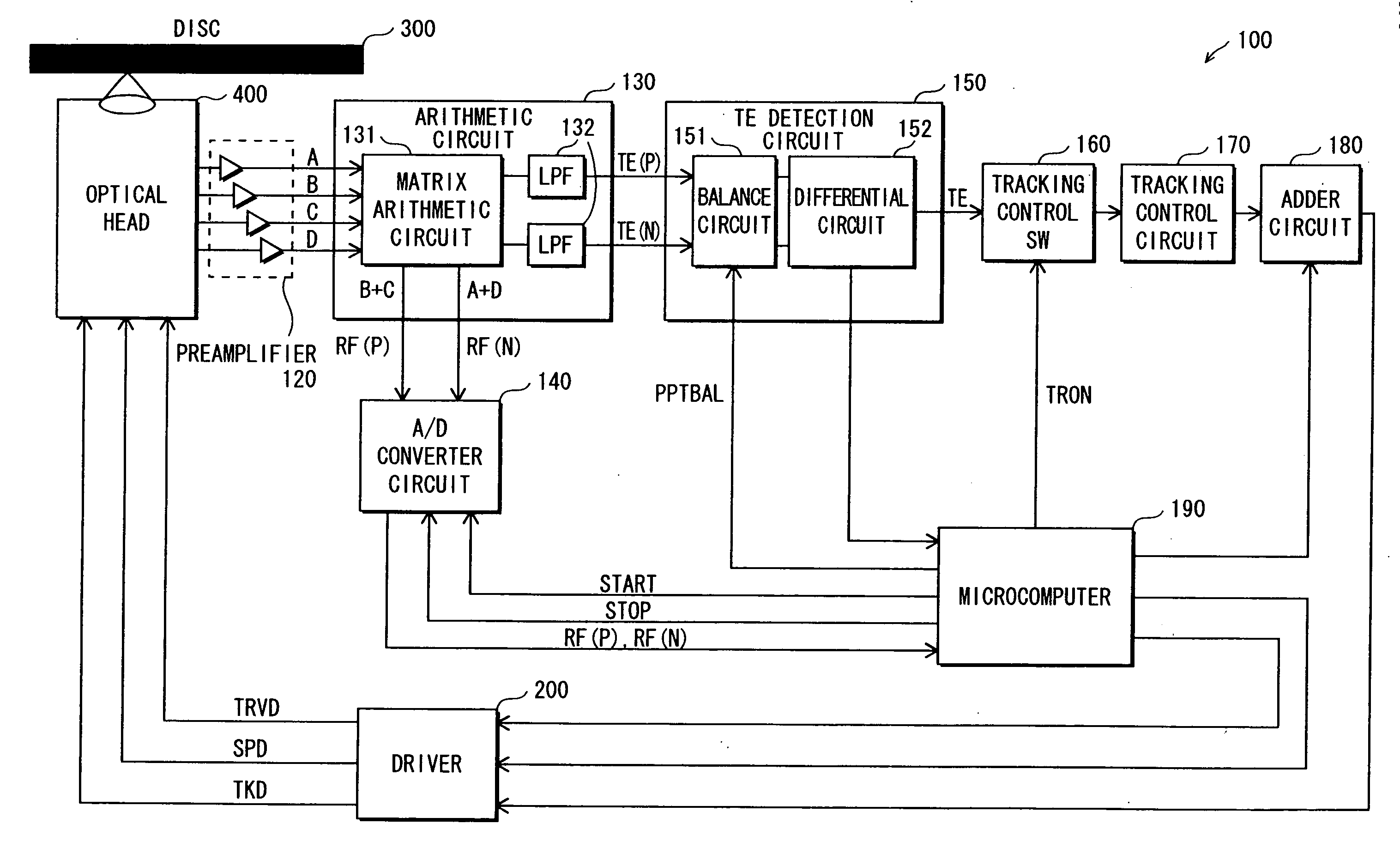
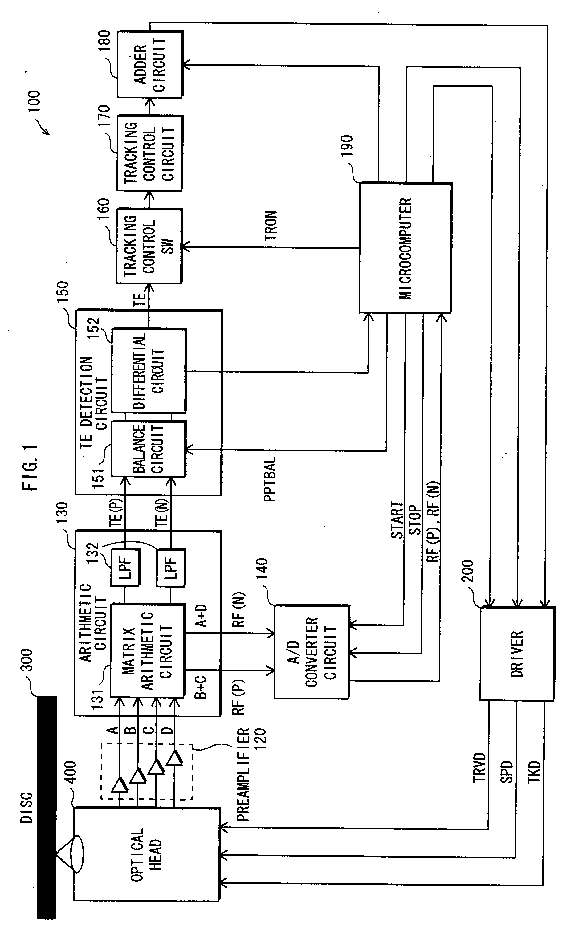
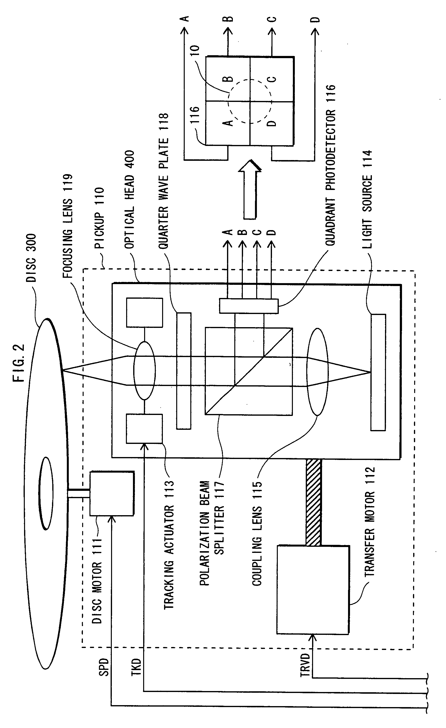
[0043] Suppose that a detecting element deviates from a position corresponding to the center line of a desired track of an optical disc at the initial state before tracking control. Due to the positional deviation of the detecting element, the beam spot on the optical disc deviates from the center line of the track. In such a case, an optical disc apparatus according to the present invention determines a correction value for correcting the positional deviation based on measurement signals and sets a focusing lens drive to move a focusing lens according the correction value. Then, the optical disc apparatus corrects a TE signal based on the symmetry of the TE signal amplitude in a conventional manner and drives a tracking control circuit based on the corrected TE signal. The tracking control is performed based on a sum signal of the correction value and a control value, which is an output value of the tracking control circuit.
[0044] In the present embodiment, a TE signal is detected...
PUM
 Abstract
Description
Claims
Application Information
 - R&D
- Intellectual Property
- Life Sciences
- Materials
- Tech Scout
- Unparalleled Data Quality
- Higher Quality Content
- 60% Fewer Hallucinations
Browse by: Latest US Patents, China's latest patents, Technical Efficacy Thesaurus, Application Domain, Technology Topic, Popular Technical Reports.
© 2025 PatSnap. All rights reserved.Legal|Privacy policy|Modern Slavery Act Transparency Statement|Sitemap|About US| Contact US: help@patsnap.com


