Method of Optimizing Routing of Demands in a Network

a network and demand technology, applied in the field of network demand optimization, can solve the problems of limiting the amount of service differential achievable, difficult to split demands across multiple paths without introducing unnecessary packet reordering, and reasonable optimization problems

Inactive Publication Date: 2007-09-13
AGILENT TECH INC
View PDF0 Cites 108 Cited by
  • Summary
  • Abstract
  • Description
  • Claims
  • Application Information

AI Technical Summary

Benefits of technology

[0021]It is therefore an object of the present invention to provide a method for optimizing routing of demands in a network which overcomes, or at least mitigates, the disadvantages of the prior art.

Problems solved by technology

Given the small size of typical core networks this optimization problem was reasonably tractable.
They represent a collection of aggregated flows and it is difficult to split these across multiple paths without introducing unnecessary packet reordering within the individual flows.
The need for service differential between flows has recently become increasingly important as operators struggle to find profitable revenue streams.
However, there is a limit to how much service differential can be achieved.
However, this can introduce additional complexity into a part of the network that is already heavily stressed.
This creates a serious scaling problem for any optimization tool (optimizer), requiring the development of techniques to decompose the problem into something more manageable.
This makes it difficult to identify LSPs that are persistent and stable enough to be worth routing offline.
One reason is that globally optimizing a large number of demands, spanning many routers, is computationally very expensive.
This cost increases rapidly as the number of demands and / or routers is increased.
Even if the demands could be routed across the whole cloud, it might not be possible to deploy such a solution because of these administrative divisions.
Another reason is due to the fact that provisioning an LSP hop-by-hop across the whole route between ingress and egress may be inefficient.
Optimizing the placement of demands across a network is computationally expensive.
An edge-based strategy has another disadvantage when the demands have additional QoS constraints attached to them.
The paths found by the optimizer may not satisfy the constraints, e.g. of delay or hop length, resulting in an invalid solution.
Attempts to enforce these constraints during the optimization process quickly lead to intractable models, even for small networks.
If only a small number of paths are used for a demand, then the size of the optimization problem can be limited to something tractable.
The downside is that the solution is only as good as the choice of paths.
The case where there are multiple paths through the access network also creates difficulties for the path-based approach.
Even a single traffic class, with demands between each pair of devices, generates a problem that would be very expensive to optimize directly.

Method used


Image

  • Method of Optimizing Routing of Demands in a Network
  • Method of Optimizing Routing of Demands in a Network
  • Method of Optimizing Routing of Demands in a Network

Examples


Embodiment Construction

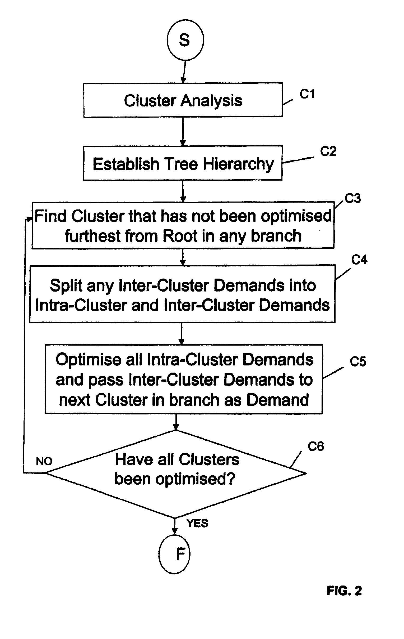
[0042]Thus, as mentioned above, it is desirable to be able to optimise routing of demands in a telecommunications network in order to increase the capacity of the network. The present invention, in a first embodiment, provides a method and apparatus for carrying out such an optimisation by analysing the network and virtually organizing the routers, or nodes, into clusters, with the clusters then being organised in a hierarchical fashion, with the network “central core” at the root of this hierarchy.

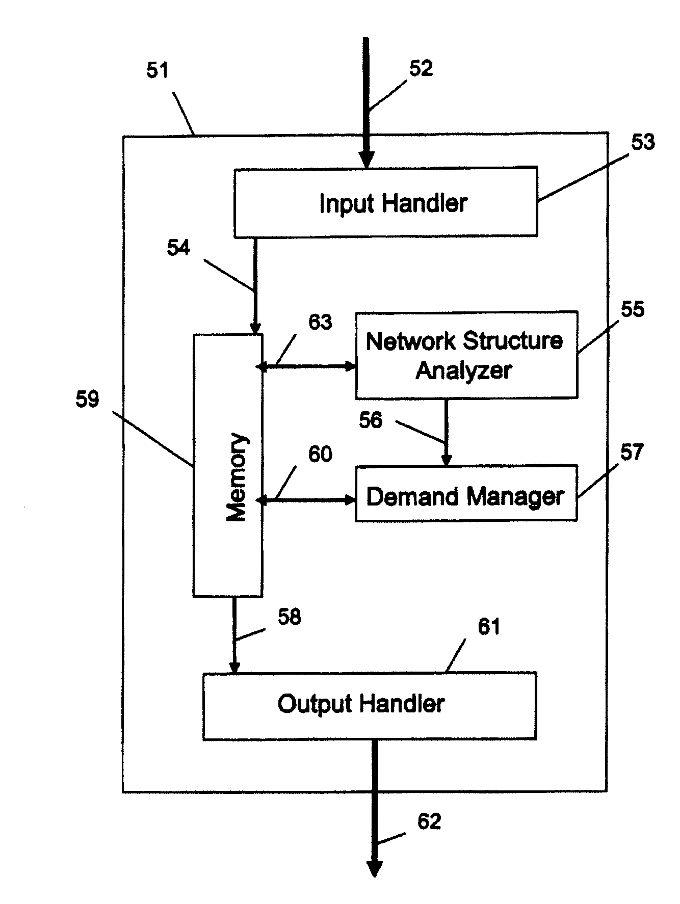
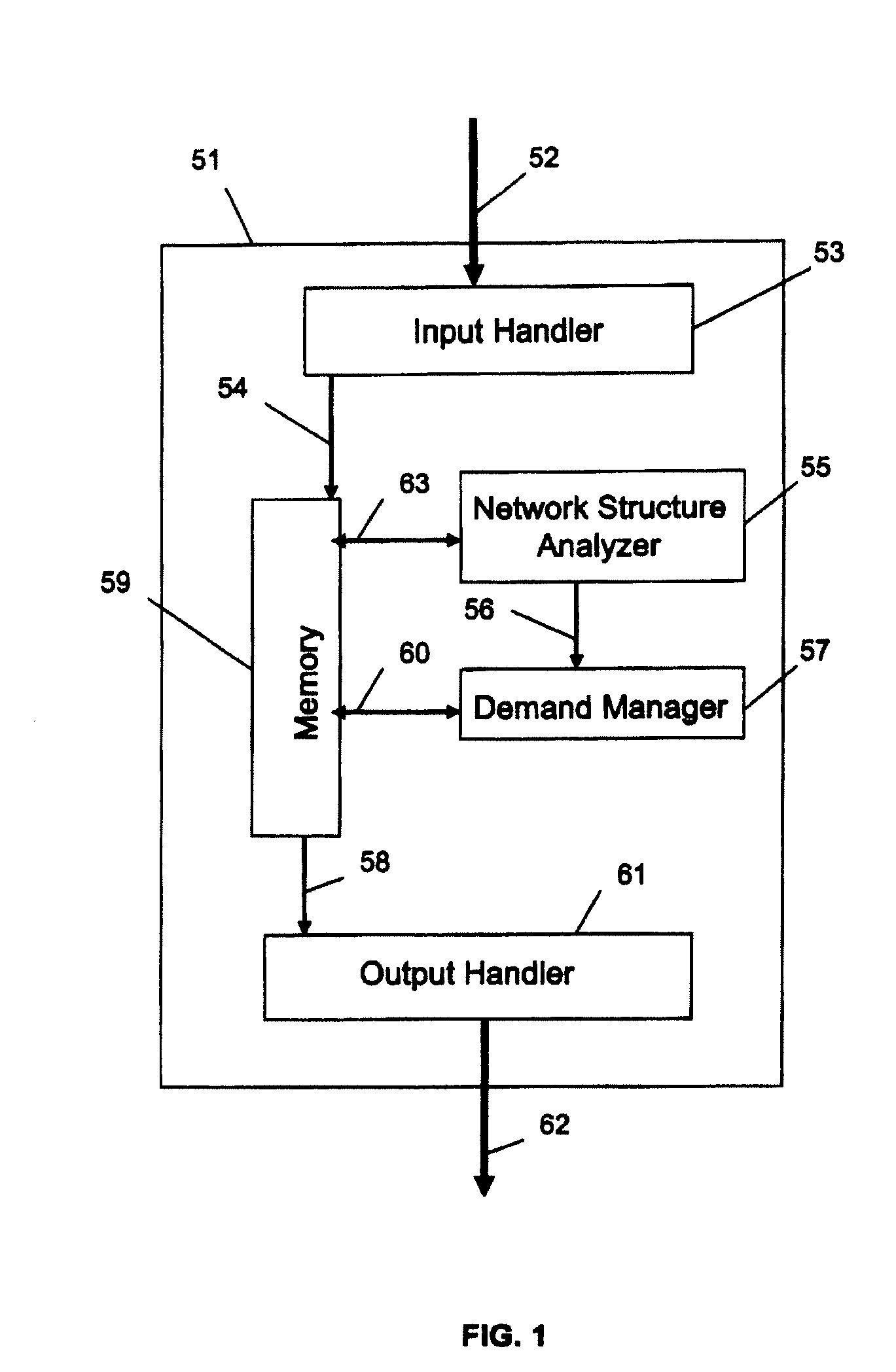
[0043]Thus, FIG. 1 is a schematic diagram showing the architecture of a demand optimizer according to a first embodiment of the present invention. The demand optimizer 51 includes an input handler 53, which receives, via input link 52, details of the network structure and demands to be optimized. The input handler 53 passes the network structure details and the demand to a memory 59 via link 54. A network structure analyser 55 is coupled to the memory 59 via two-way link 63 and performs a...


PUM


Abstract

The present invention relates to a method for optimization of demands in a packet switched communication network, especially, though not exclusively, for the optimization of demands in a Multi Protocol Label Switching (MPLS) packet switched communication network. The present invention provides a method to enable network nodes, such as routers to be clustered into components, with the components organised in a hierarchical fashion, and with the network “core” at the root of this hierarchy. Demands that originate or terminate at components outside the core, but that traverse the core, are temporarily replaced by demands that originate and terminate within the core component. Having optimized the resulting set of demands it is then shown how to use the solution to satisfy the original demands. Multi-access networks cause some complications, and these are taken into account. Also, further demand replacement methods have been developed that take into account complex access situations, In particular, as mentioned, the case has been considered, where there is an existing partitioning of the routers, e.g. into core and access routers, which needs to be respected.

Description

[0001]The present invention relates to a method and apparatus for optimizing routing of demands in a network, especially, though not exclusively, for the optimization of demands in a packet switched communication network, such as a Multi Protocol Label Switching (MPLS) packet switched communication network.BACKGROUND OF THE INVENTION[0002]MPLS is used in communication networks, specifically in Asynchronous Transfer Mode (ATM) and Internet Protocol (IP) networks to provide additional features, for example, precise control over routing, allowing for improved customer services. MPLS was originally developed to enhance performance and network scalability. A working group within the IETF (Internet Engineering Task Force) does standardization work on this topic, which is documented in “Requests for Comment” (RFCs).[0003]In a packet switched network, as is well known, packets of data are routed over a plurality of links from a start point to a destination point. The links are coupled toget...

Claims


Application Information

Patent Timeline
Patent Type & Authority Applications(United States)
IPC IPC(8): H04J3/14H04L12/56
CPCH04L45/04H04L45/50H04L45/46H04L45/302H04L41/044
Inventor MITCHELL, KEVIN
Owner AGILENT TECH INC
Why Eureka
Try Eureka