Unlock instant, AI-driven research and patent intelligence for your innovation.

Emitter pulse detection utilizing adaptive matched filter approach

a filter and filter technology, applied in the field of electronic support measures, can solve the problem that the information associated with pulses from em emitters can be lost in the background noise collected at the receiver platform

Inactive Publication Date: 2007-09-13
LOCKHEED MARTIN CORP
View PDF17 Cites 12 Cited by
  • Summary
  • Abstract
  • Description
  • Claims
  • Application Information

AI Technical Summary

Problems solved by technology

Accordingly, information associated with pulses from EM emitters can be lost in the background noise collected at the receiver platform.

Method used


Image

  • Emitter pulse detection utilizing adaptive matched filter approach
  • Emitter pulse detection utilizing adaptive matched filter approach
  • Emitter pulse detection utilizing adaptive matched filter approach

Examples


Embodiment Construction

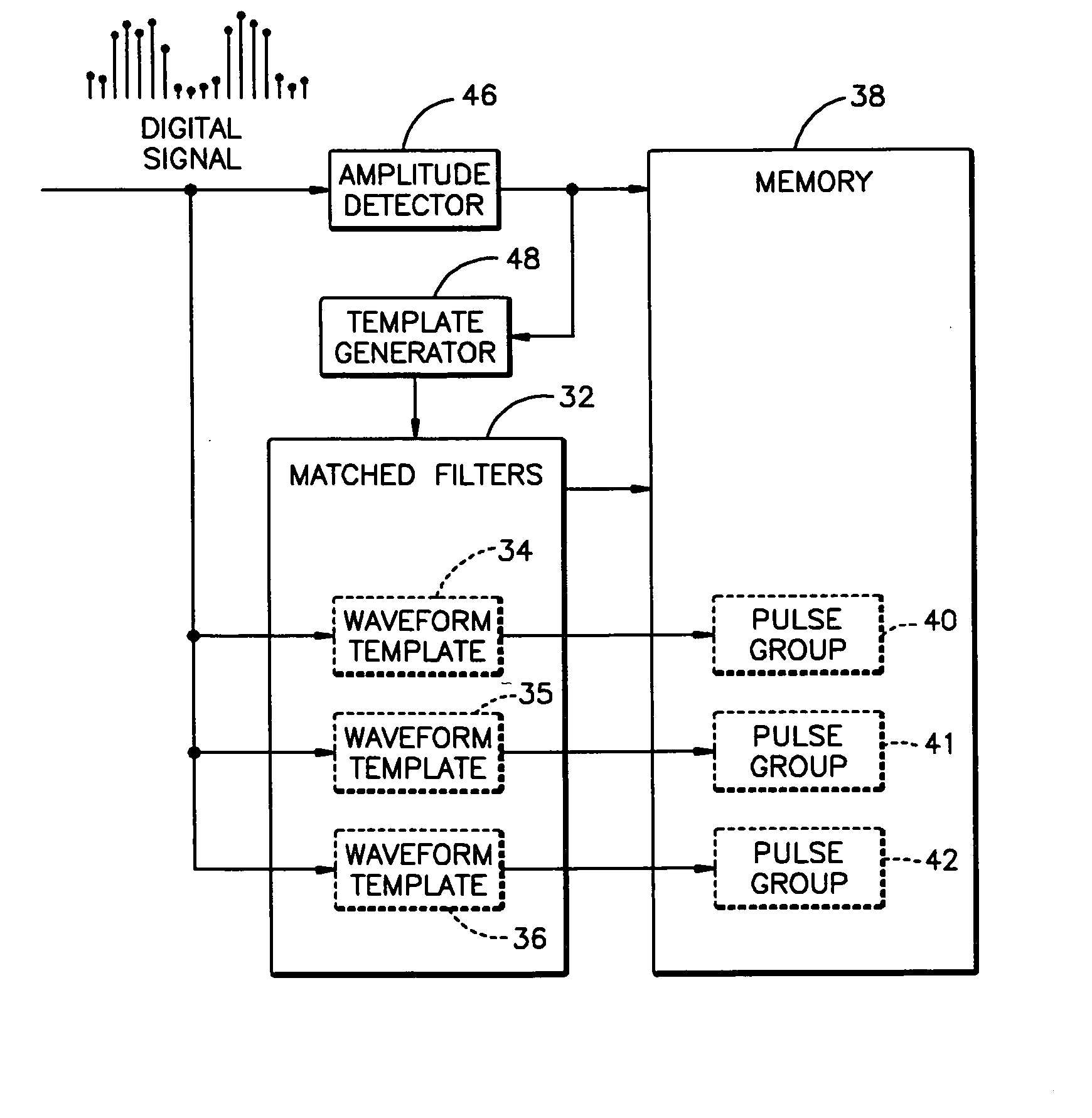
[0015] In accordance with an aspect of the present invention, methods and systems for identifying emitter pulses are provided. The methods and systems can be applied to any of a number of applications in which it is desirable to detect an emitter pulse, such as the detection and location of radar emissions. A pulse detection system in accordance with one aspect of the present invention includes a plurality of matched filters that detect portions of the digital signal that match associated templates. An amplitude-based pulse detector detects pulses that do not match one of the associated templates. The detected pulses at the amplitude-based pulse detector can be utilized to create additional matched filters.

[0016]FIG. 1 illustrates a pulse detection system 10 for an electronic support measures (ESM) system in accordance with an aspect of the present invention. The pulse detection system 10 detects and characterizes radar pulses detected by the system to determine properties of one o...


PUM


Abstract

Systems and methods are provided for dynamically analyzing radar pulses at a receiver. A digital signal is provided to an amplitude detector. At least one digital waveform representing an emitter pulse is identified at the amplitude detector. A matched filter associated with the emitter is generated, comprising at least one characteristic of the identified digital waveform.

Description

BACKGROUND OF THE INVENTION [0001] 1. Technical Field [0002] The invention relates generally to electronic support measures and, more specifically, to systems and methods for the detection of emitter pulses. [0003] 2. Description of the Prior Art [0004] Determining the location of emitters of electromagnetic (“EM”) radiation in a monitored area, especially multiple emitters in an area, is a matter of interest in many applications, such as military or security applications. In one such application, it is desirable to determine the location of EM emitters in a monitored geographic area. Known methods for determining the location of EM emitters involve collecting electromagnetic radiation data simultaneously at one or more EM receiver platform sites having known locations in the monitored area. The EM data collected at the EM receiver platforms may be filtered in order to isolate a particular frequency range of interest. [0005] Once the EM data is collected, it is necessary to separate...

Claims


Application Information

Patent Timeline
IPC IPC(8): H04L27/06
CPCH04L27/08
Inventor JOHNSON, J. ANDREW
Owner LOCKHEED MARTIN CORP