Tapered fiber bundle apparatus with monitoring capability

a fiber bundle and apparatus technology, applied in the field of fiber optic systems, can solve the problems of limiting the ability of amplifiers to produce high output power, interference between multiple signals, and many operational obstacles in the propagation of high-power laser light through various propagation media

Inactive Publication Date: 2007-09-13
RPX CORP
View PDF15 Cites 27 Cited by
  • Summary
  • Abstract
  • Description
  • Claims
  • Application Information

AI Technical Summary

Problems solved by technology

The propagation of high power laser light through various propagation media incurs many operational obstacles, however.
These reflections limit the ability of an amplifier to produce high output powers.
Interaction between the multiple signals creates, among other things, sidebands and modulation instability.
However, the longer the

Method used


Image

  • Tapered fiber bundle apparatus with monitoring capability
  • Tapered fiber bundle apparatus with monitoring capability
  • Tapered fiber bundle apparatus with monitoring capability

Examples


Embodiment Construction

[0026] One or more specific embodiments of the present invention will be described below. In an effort to provide a concise description of these embodiments, not all features of an actual implementation are described in the specification. It should be appreciated that in the development of any such implementation, as in any engineering or design project, numerous implementation specific decisions must be made to achieve the developer's specific goals, such as compliance with system related and business related constraints, which may vary from one implementation to another. Moreover, it should be appreciated that such a development effort might be complex and time consuming but would nevertheless be a routine undertaking of design, fabrication, and manufacture for those of ordinary skill having the benefit of this disclosure.

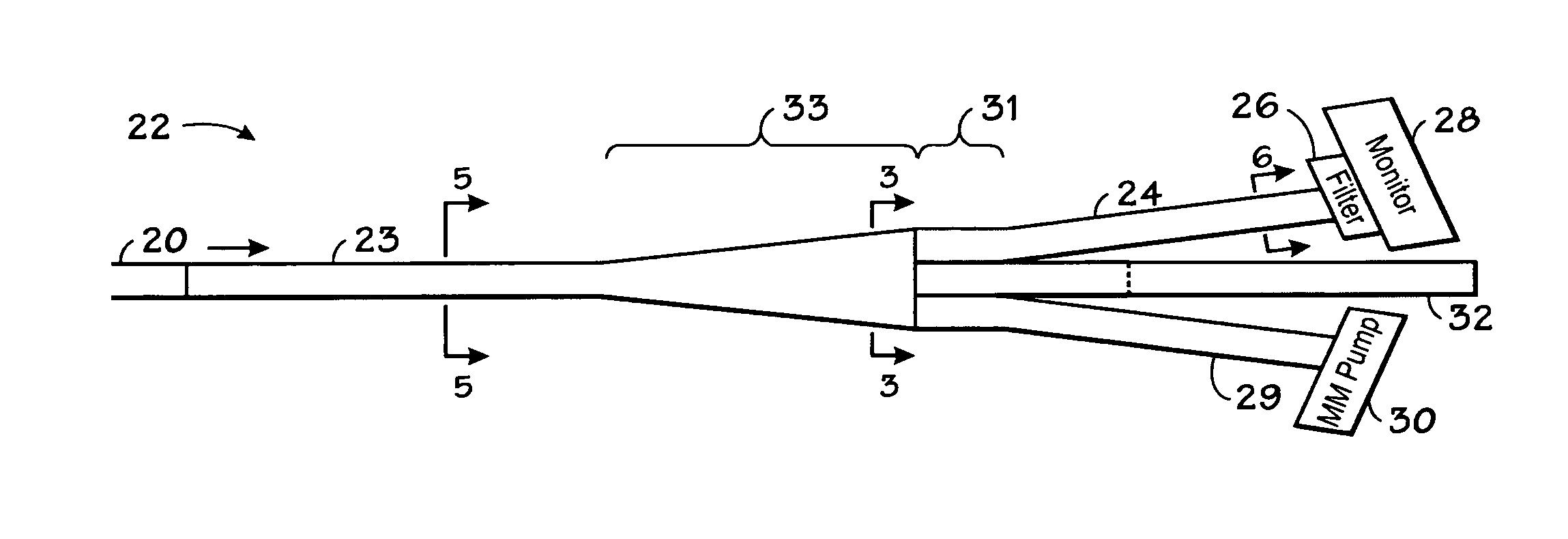
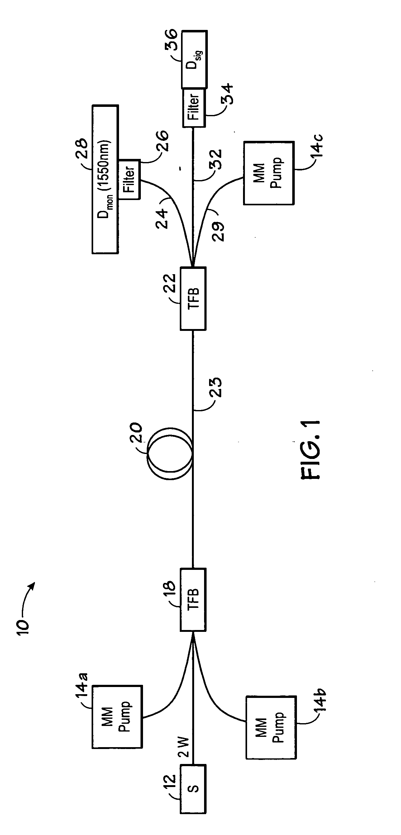
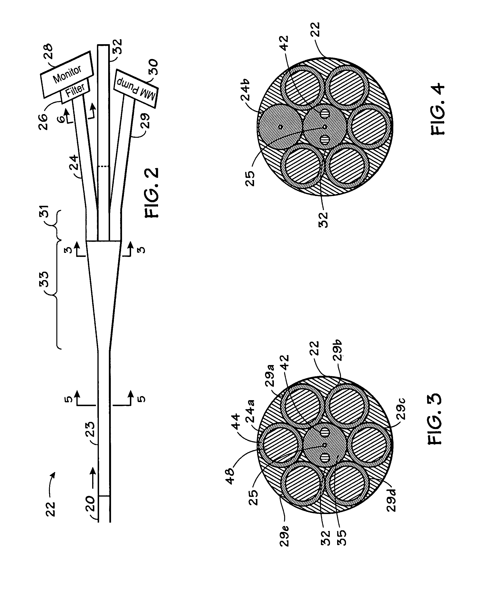
[0027] The output of an optical amplifier may be monitored without extending the length of the signal path in a system using a tapered fiber bundle to cladding ...


PUM


Abstract

Systems and methods for monitoring signals in an optical fiber amplifier system are provided. The optical amplifier system includes a tapered fiber bundle which couples optical energy into the cladding of an optical amplifier. A signal passing through the optical amplifier is amplified. To monitor the amplified signal, a single fiber of a tapered fiber bundle may be used as a monitor fiber. Alternatively, a monitor or coupler may be integrated into the tapered fiber bundle during manufacturing. The systems and methods disclosed allow for monitoring the amplified signal without increasing the length of the amplified signal's path, thus minimizing the introduction of additional non-linearities.

Description

STATEMENT OF GOVERNMENT FUNDED RESEARCH [0001] The U.S. Government has a paid-up license in this invention and the right in limited circumstances to require the patent owner to license others on reasonable terms as provided for by the terms of Grant No. NRO 000-04-C-226 awarded by the National Aeronautics and Space AdministrationBACKGROUND [0002] 1. Field of the Invention [0003] The present invention relates generally to fiber optic systems. More specifically, the invention relates to a method and apparatus for monitoring a laser signal in high power optical fiber amplifiers and lasers. [0004] 2. Description of the Related Art [0005] This section is intended to introduce the reader to various aspects of art, which may be related to various aspects of the present invention that are described and / or claimed below. This discussion is believed to be helpful in providing the reader with background information to facilitate a better understanding of the various aspects of the present inve...

Claims


Application Information

Patent Timeline
IPC IPC(8): G02B6/26
CPCG02B6/04H01S3/094007H01S3/06754H01S3/06745
Inventor WYSOCKI, PAUL F.
Owner RPX CORP
Why Eureka
Try Eureka