Method and apparatus for converting semiautomatic key cutting machines to automatic operation

a semi-automatic, cutting machine technology, applied in the direction of process control, process control, instruments, etc., can solve the problems of repetitive physical tasks, high cost, physical strain on wrist and arm muscles,

Inactive Publication Date: 2007-09-13
ZAHEDI MEHDI
View PDF3 Cites 4 Cited by
  • Summary
  • Abstract
  • Description
  • Claims
  • Application Information

AI Technical Summary

Benefits of technology

[0006] (a.) To provide a method and apparatus for automatically positioning the vise of a semiautomatic key cutting machine having a crank wheel. Such automatic positioning of the vise of a semiautomatic key cutting machine frees the operator to perform other tasks while a key is being cut, and reduces physical repetitive stress on the operator's wrist and arm.
[0007] (b) To provide a method and apparatus for automatically turning the crank wheel of a semiautomatic key cutting machine at the optimum speed so as to minimize cutting time while simultaneously protecting the expensive cutting wheel from damage.
[0008] (c) To provide an easily installed method and apparatus for automatically turning the crank wheel of a semiautomatic key cutting machine thereby obviating the necessity for drilling holes soldering electrical connections or otherwise modifying an existing semiautomatic key cutting machine.

Problems solved by technology

Such machines are of considerable utility to professional locksmiths, but are relatively expensive.
Cutting a single key may require the operator to perform from ten to twenty rotations of the crank wheel in each direction thereby causing physical strain to wrist and arm muscles.
It is also necessary for the operator to have a certain amount of skill since turning the crank wheel at the wrong speed while cutting a key can damage the expensive cutting wheel.
Furthermore, the operator is required to perform a repetitive physical task namely turning the crank wheel.
While this task is not physically exhausting, it does require a repetitive physical stress on the arm and wrist that can lead to medical problems such as carpal tunnel syndrome.
Unfortunately, the operator must still attend the key cutting machine for the duration of a cutting session and cannot use this time to attend other tasks.

Method used


Image

  • Method and apparatus for converting semiautomatic key cutting machines to automatic operation
  • Method and apparatus for converting semiautomatic key cutting machines to automatic operation
  • Method and apparatus for converting semiautomatic key cutting machines to automatic operation

Examples


Embodiment Construction

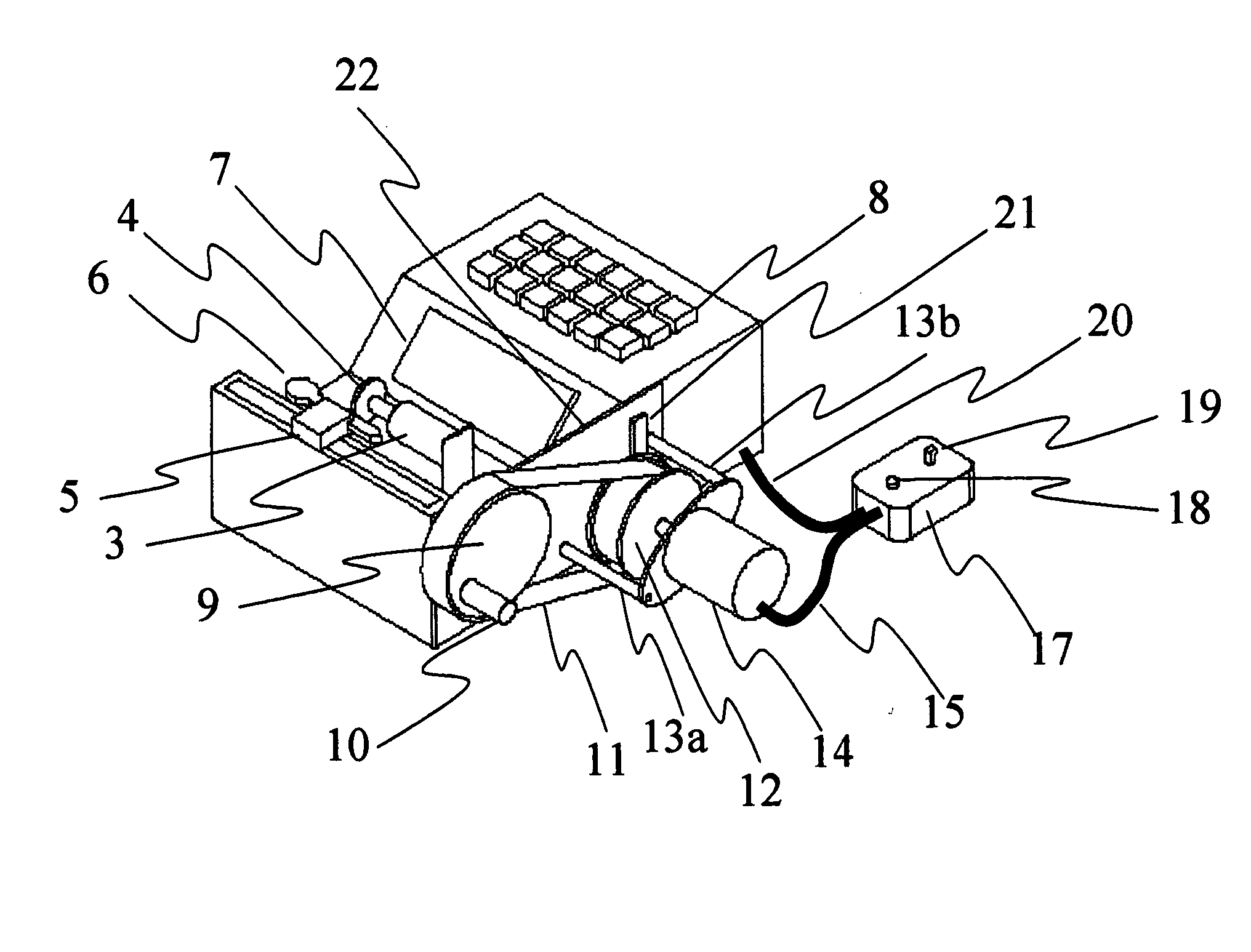
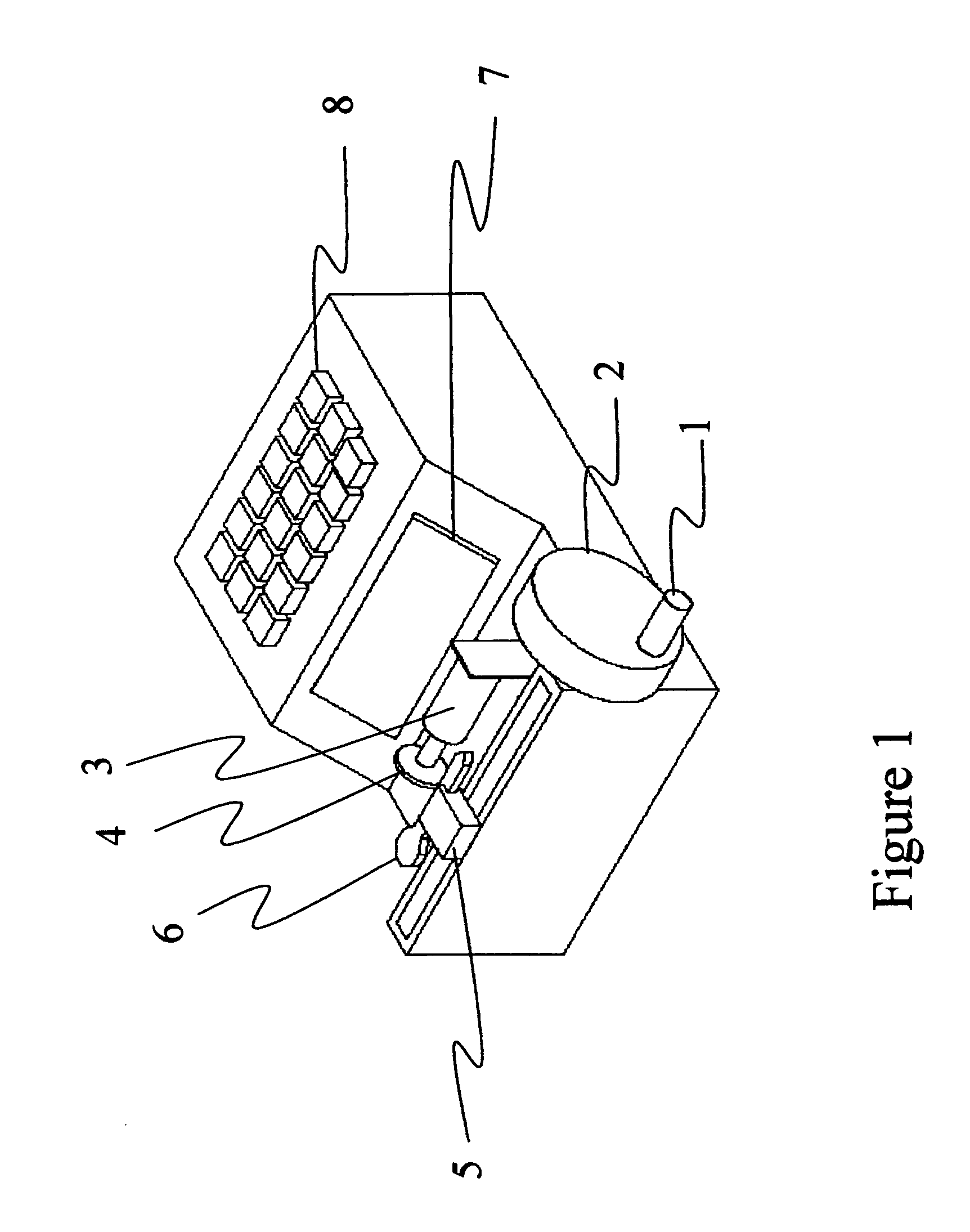
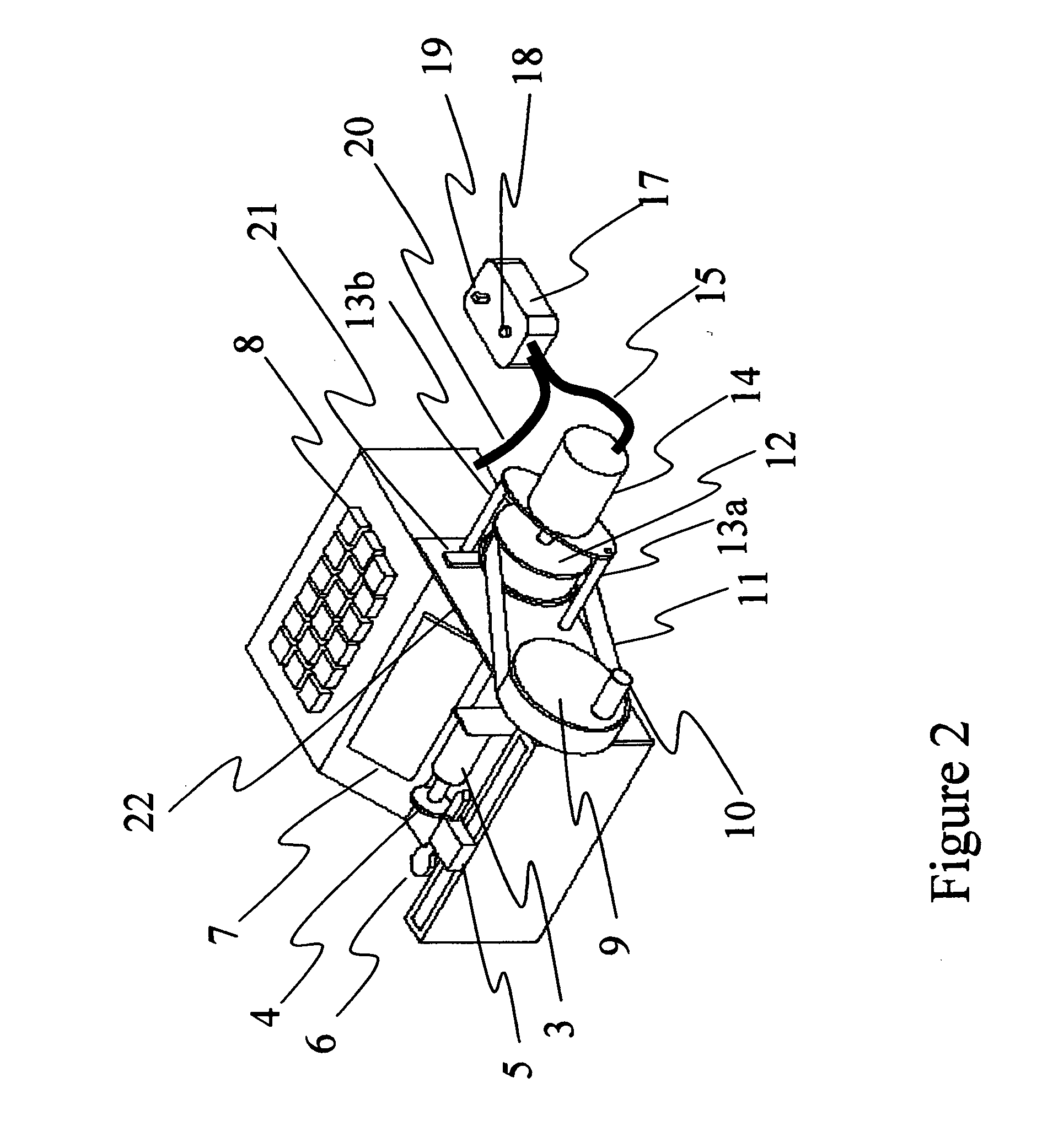
[0045] Referring to the drawings, FIG. 1 is a drawing of a semiautomatic key cutting machine before installation of the present invention. To cut a key, the operator applies electrical power to the machine, and follows the directions shown in display window 7. It is often necessary for the operator to turn crank wheel 2 using crank handle 1 to the right and left to position the vise in its starting or “home” position. The operator uses keyboard 8 to enter the appropriate code for the key to be cut. The operator then inserts a suitable blank key 6 into vise 5. After fastening the key in the vice, the operator turns crank wheel 2 using crank handle 1 in accordance with the instructions given in display window 7. Turning crank wheel 2 causes vise 5 to move to the right or left depending on whether the crank wheel is turned clockwise or counterclockwise. When the operator has turned crank wheel 2 the appropriate number of turns in the appropriate direction, cutting motor 3 is automatica...


PUM

PropertyMeasurementUnit
poweraaaaaaaaaa
physical strainaaaaaaaaaa
speedaaaaaaaaaa

Abstract

A semiautomatic key cutting machine is converted to fully automatic operation. The conversion involves sending available electrical signals and power from the existing semiautomatic key cutting machine to a controller in the conversion apparatus. The signals are used by the controller to operate an external motor that is coupled to the crank wheel of the semiautomatic key cutting machine. The apparatus thereby controls the crank wheel leaving the operator to perform other tasks while a key is being cut. The apparatus can be coupled to the crank wheel of any existing semiautomatic key cutting machine without permanent or irreversible modification to the existing key cutting machine.

Description

BACKGROUND OF THE INVENTION [0001] This invention relates to semiautomatic key cutting machines as may be used by professional locksmiths, specifically to such machines as may have computer control of the cutting functions and manual control of the position of the key holding vise. [0002] Machines for cutting keys automatically have been available for several years. One example is disclosed in U.S. Pat. No. 5,997,224 to Beauregard et al in 1999. These are computer controlled machines in which the locksmith enters relevant data into the machine's computer by means of a computer keypad, clamps a key blank into the machine's vice, and pushes a button to start the machine cutting the desired pattern of notches into the key blank. The operator need not attend the machine while it is cutting a new key, but may attend to other business. Such machines are of considerable utility to professional locksmiths, but are relatively expensive. [0003] Another class of key cutting machines is referre...

Claims


Application Information

Patent Timeline
Patent Type & Authority Applications(United States)
IPC IPC(8): B23C3/35
CPCB23C3/35B23C2235/24Y10T409/300952G05B2219/50168Y10T409/303808G05B2219/45245
Inventor ZAHEDI, MEHDI
Owner ZAHEDI MEHDI
Why Eureka
Try Eureka