Turbomachine

a technology of turbines and motors, applied in the direction of wind motors with parallel air flow, wind motors with perpendicular air flow, liquid fuel engine components, etc., can solve the problems of high repair costs, increased wear, and high repair costs, and achieve the effect of reducing operating costs or maintenance costs

Inactive Publication Date: 2007-09-13
ANSALDO ENERGIA SWITZERLAND AG
View PDF20 Cites 23 Cited by
  • Summary
  • Abstract
  • Description
  • Claims
  • Application Information

AI Technical Summary

Benefits of technology

[0017] The invention is intended to remedy this. One aspect of the present invention is concerned with the problem of specifying, for a turbomachine of the aforementioned type, an improved embodiment which is distinguished particularly by reduced operating costs or maintenance costs.
[0018] Another aspect of the present invention includes the general idea of coupling the shroud plates forming the shroud to one another in such a way that they can transmit tensile forces between one another in the circumferential direction. With a corresponding arrangement on the respective blades or vanes, a self-supporting structure for the shroud can thereby be achieved, at least in the case of moving blades, when the turbomachine is in operation. The self-supporting shroud thus formed can absorb in itself the forces occurring during operation, particularly in the case of a moving blade row, without in this case subjecting the blades to load. This is achieved by means of the circumferentially closed continuous tensile force coupling of adjacent shroud plates to one another, with the result that the centrifugal forces which occur are converted into tangential tensile stresses. So that the shroud plates can be mounted on the blades, the shroud plates must be components produced separately from the blades. The separate production of the shroud plates makes it possible to use a material which differs from that of the blades and / or a material structure which differs from that of the blades. For example, the shroud plates may be optimized in terms of tensile load in the circumferential direction, while the blades are conventionally optimized in terms of tensile load in the radial direction.
[0019] A multimembered self-supporting shroud ring embodying principles of the present invention has the advantage, when used in a moving blade row, that it can absorb in itself the centrifugal forces occurring during operation, without a significant additional radial tensile load on the moving blades in this case arising. The lifetime of the moving blades is thereby increased. The moving blades may likewise have a lower dimensioning, which can be utilized for a weight reduction increasing the efficiency of the turbomachine.
[0020] Furthermore, the shroud plates designed as separate components can readily be formed in such a way that they can be demounted comparatively simply again. This simplifies the repair or replacement of the shroud plates in the event of wear phenomena. This is advantageous particularly in the case of rotor portions having integrated moving blades.
[0021] A further advantage is seen in that these shroud plates are basically retrofittable. Blade rows of a turbo-machine can thereby be provided with a shroud at a later stage in a comparatively cost-effective way, so that the advantages of a shroud, to be precise, the stabilization of long blades via coupling and an increase in efficiency due to reduced leakages and improved aerodynamics, can thereby be utilized.

Problems solved by technology

Insofar as the shrouds are used as axial seals for individual blade rows, they may be exposed to increased wear, with the result that repairs are required.
Since the individual shroud plates or shroud portions, which in their entirety form the respective shroud in the mounted state, form an integral part of the associated blade, high repair costs are incurred, since the entire blade has to be repaired and, if appropriate, exchanged.
Furthermore, in the case of moving blades, the individual shroud portions or shroud plates are exposed to extreme centrifugal forces.
Moving blades which have an integral shroud plate are under a correspondingly high tensile load, with the result that the service life of the individual moving blade is reduced.

Method used


Image

  • Turbomachine
  • Turbomachine
  • Turbomachine

Examples


Embodiment Construction

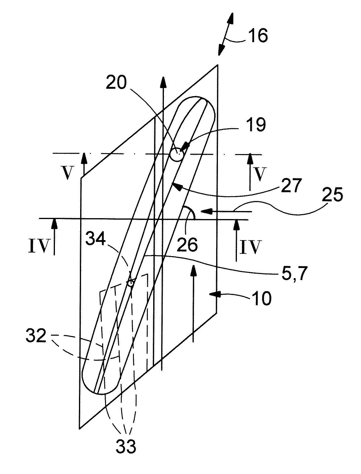
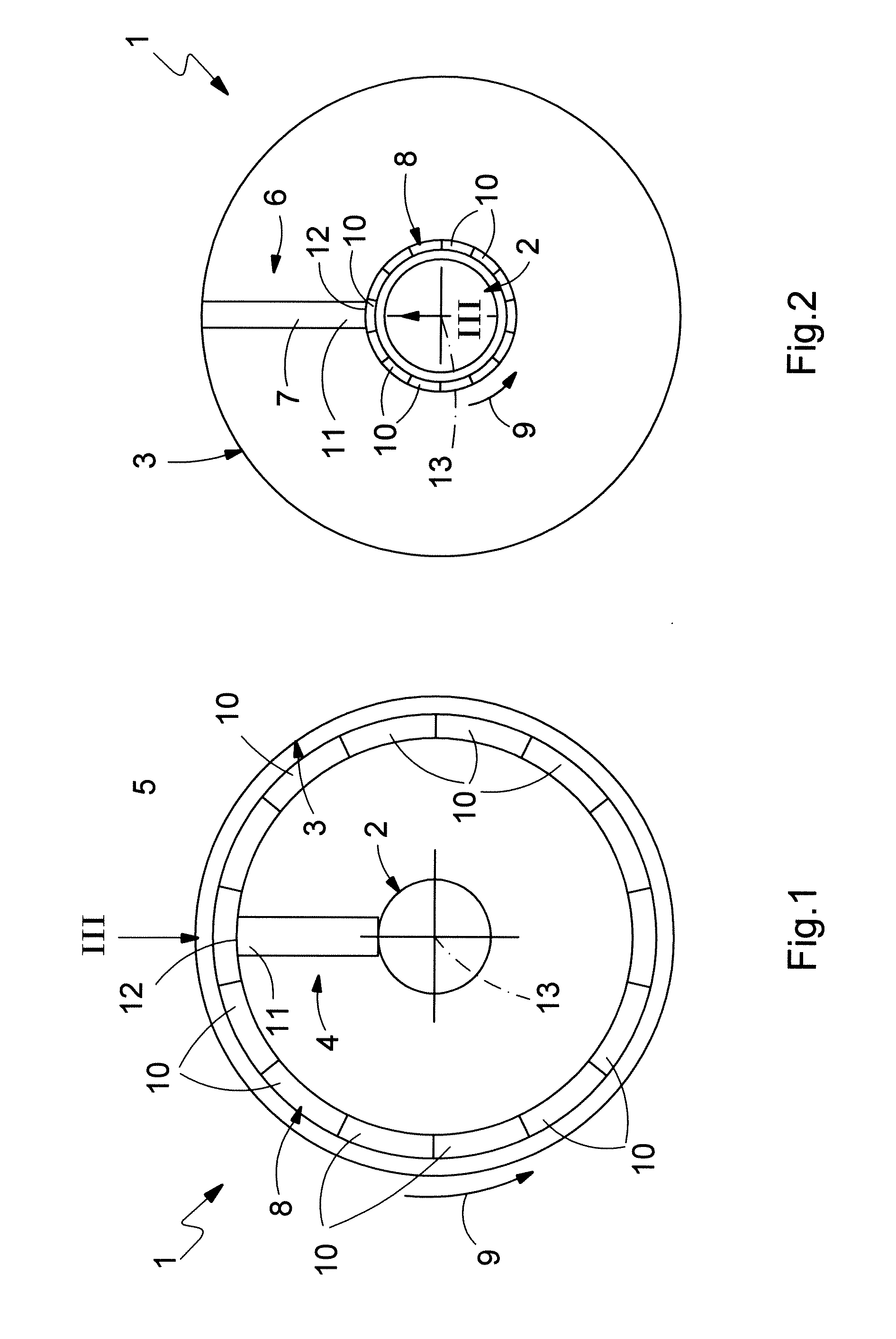
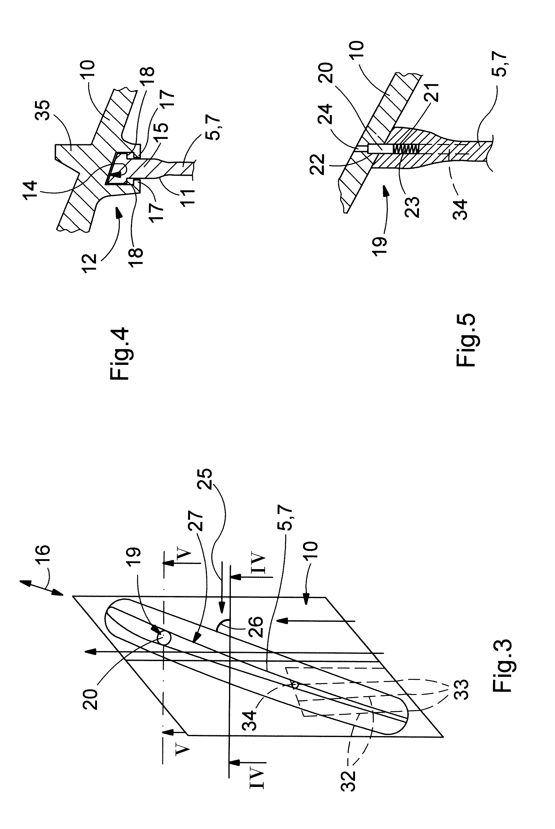
[0031] According to FIGS. 1 and 2, a turbomachine 1 is equipped with a rotor 2 and with a stator 3. The rotor 2 is mounted rotatably in the stator 3 in the usual way. The turbomachine 1 may basically be a compressor or a turbine. Where a turbine is concerned, this may be a steam turbine or a gas turbine. The turbomachine 1 may be stationary and serve, for example in a power plant, for driving a generator. The turbomachine 1 may likewise be a drive assembly in a vehicle, in particular in an aircraft. Preferably, however, the invention is implemented by the turbomachine 1 being designed as a stationary gas turbine.

[0032] According to FIG. 1, the rotor 2 has at least one moving blade row 4 which includes a plurality of moving blades 5. The cross section according to FIG. 1 lies in the region of such a moving blade row 4, although only a single moving blade 5 is illustrated for clarity. In contrast to this, according to FIG. 2, the stator 3 has at least one guide vane row 6 which inclu...


PUM


Abstract

A turbomachine (1), in particular a turbine or compressor, includes a rotor (2) which has at least one moving blade row (4) with a plurality of moving blades (5), and a stator (3) which has at least one guide vane row (6) with a plurality of guide vanes (7), at least in one of the blade or vane rows (4, 6) all the blades or vanes (5, 7) each having a shroud plate (10). In order to simplify the maintenance of the turbo-machine (1), the shroud plates (10) are separate components with respect to the respective blade or vane (5, 7) and are mounted on the respective blade or vane (5, 7), shroud plates (10) adjacent in the circumferential direction (9) being coupled to one another for the transmission of tensile forces in the circumferential direction (9).

Description

[0001] This application claims priority under 35 U.S.C. § 119 to Swiss patent application number 01510 / 05, filed 15 Sep. 2005, the entirety of which is incorporated by reference herein. BACKGROUND OF THE INVENTION [0002] 1. Field of the Invention [0003] The present invention relates to a turbomachine, in particular a turbine or a compressor, and, moreover, to a shroud plate for blades or vanes of a turbomachine of this type. [0004] 2. Brief Description of the Related Art [0005] Turbomachines, such as turbines, in particular gas turbines and steam turbines, and also compressors, include a rotor which is mounted rotatably in a fixed stator. Turbomachines of this type are also designated as rotating turbomachines. The rotor in this case usually includes a plurality of moving blade rows which each include a plurality of moving blades. Correspondingly, the stator normally has a plurality of guide vane rows which each include a plurality of guide vanes. [0006] In this context, it is basic...

Claims


Application Information

Patent Timeline
Patent Type & Authority Applications(United States)
IPC IPC(8): F04D29/08
CPCF01D5/225Y02T50/672F05D2260/30F05D2240/40Y02T50/673Y02T50/60F05D2260/36
Inventor FERBER, JOERGENRITCHIE, JAMES
Owner ANSALDO ENERGIA SWITZERLAND AG
Why Eureka
Try Eureka