Magnetic suspension pumps

a technology of suspension pump and magnetism, which is applied in the direction of piston pump, pump components, positive displacement liquid engine, etc., can solve the problems of reduced power exchanging efficiency of the pump, low pump power efficiency, and relatively short service life, so as to reduce power consumption and reduce the need for replacement. , the effect of increasing the service li

Inactive Publication Date: 2007-09-13
ZHAO HUIXIA
View PDF3 Cites 6 Cited by
  • Summary
  • Abstract
  • Description
  • Claims
  • Application Information

AI Technical Summary

Benefits of technology

[0011] 1. The piston fit within the cylinder of the invention works at a magnetically suspended situation without friction between the piston and the cylinder, which thereby renders the piston pump of a higher efficiency and lower power consumption. The power consumption of the invention is generally about half that of a conventional piston pump.
[0012] 2. The piston pump of the present invention is durable and reliable and in no need of replacement of any parts. Moreover, the piston pump of the invention shows more advantageous when it is employed in an apparatus which needs to work continuously, such as a medical device.

Problems solved by technology

The conventional piston pump has disadvantages that it is of a relatively short service life and includes some easily worn-out parts, for a contact between a piston and a pump will lead to abrasion.
Moreover, resistance generated due to the friction or tension between the portions of the pump (especially working at a high speed) gives rise to a low power efficiency of the pump.
That is, power exchanging efficiency of the pump is reduced.

Method used


Image

  • Magnetic suspension pumps
  • Magnetic suspension pumps
  • Magnetic suspension pumps

Examples


Embodiment Construction

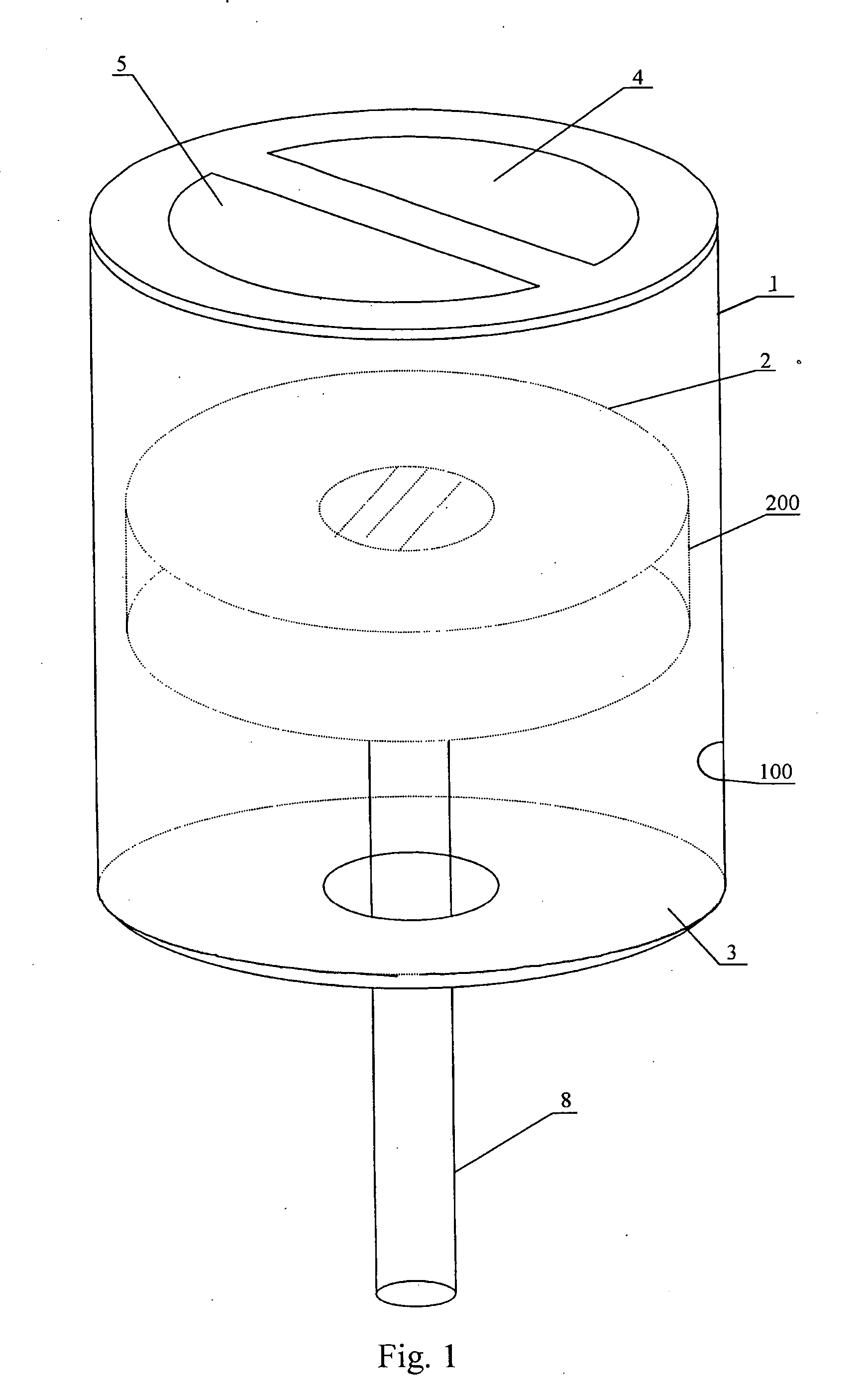
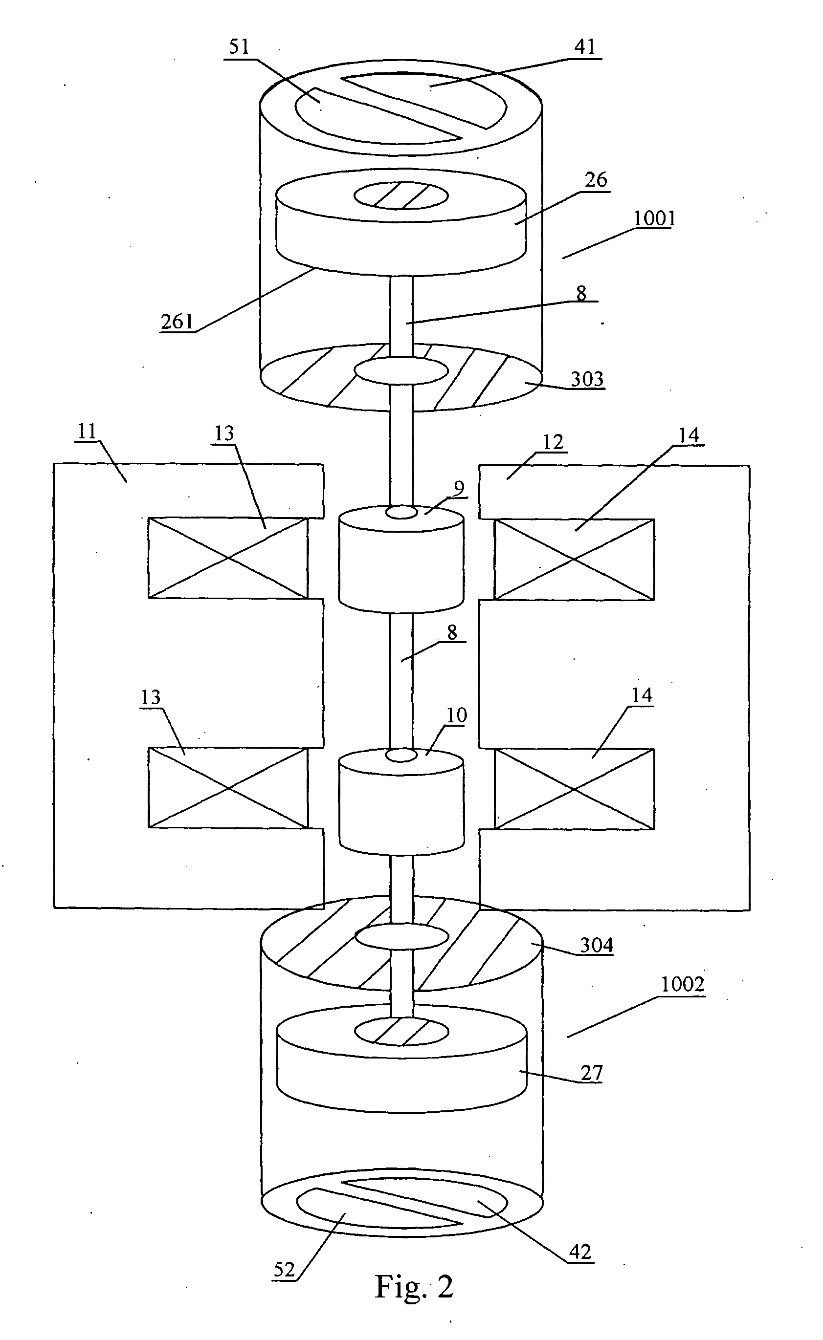
[0018] The present invention and various advantages thereof will be described with reference to exemplary embodiments in conjunction with the drawings.

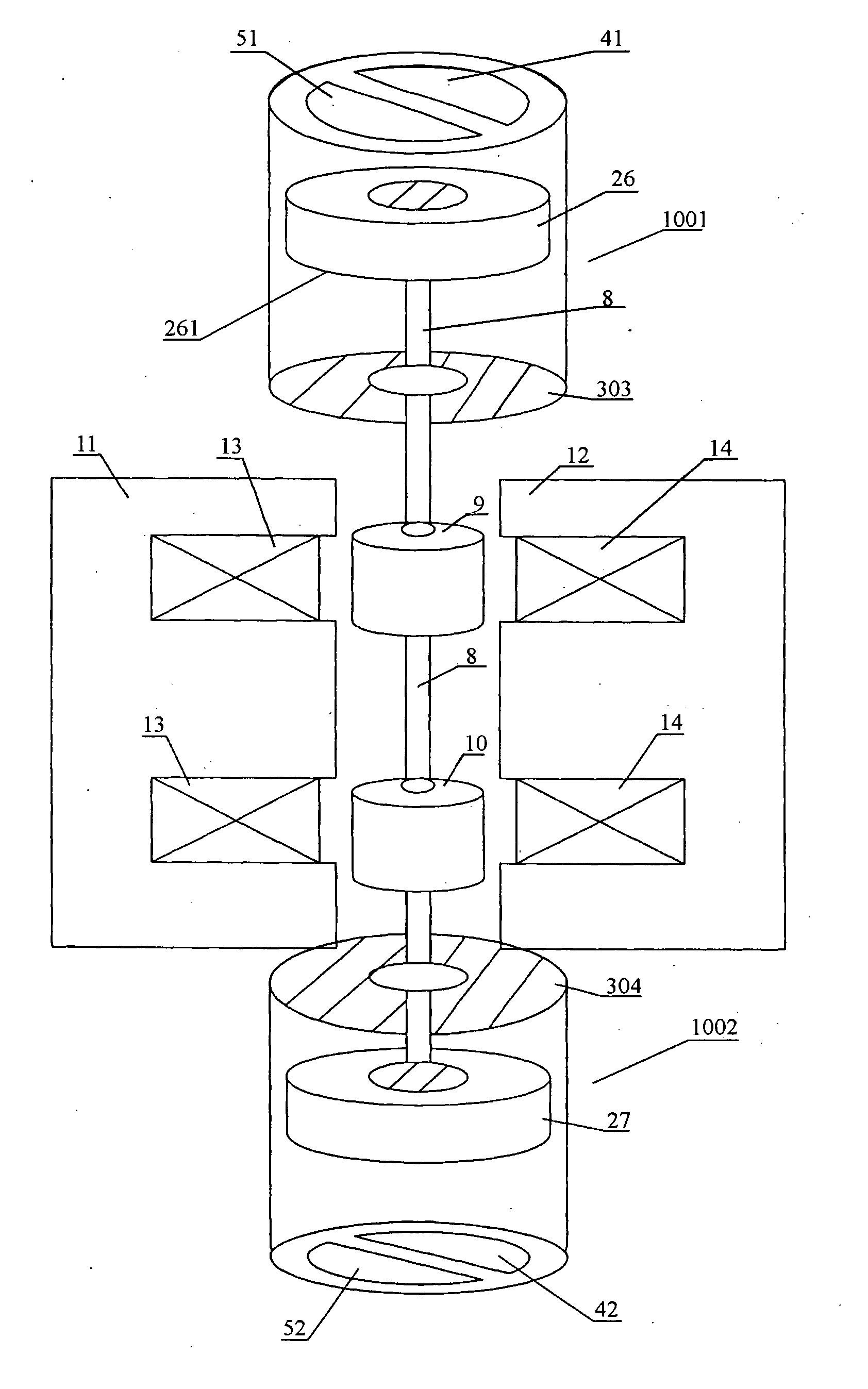
[0019] Refer to FIGS. 1-5, a magnetically suspended piston pump of the present invention mainly comprises a cylinder 1 made of a cylindrical permanent magnet, a piston 2 made of a circular permanent magnet, a circular magnetic plate 3 located at an end of the cylinder 1, an inlet valve 4 and an outlet valve 5 located at another end of the cylinder 1, and a magnetic connecting rod driving device 8.

[0020] The piston 2 of the pump is magnetically suspended within the cylinder 1, and fulfills compression or suction of the liquid / gas by moving up and down within the cylinder 1. In practice, the cylinder 1 can be a permanent magnet which generates a uniform magnetic field at an inner surface 100 of the cylinder 1. That is, the intensity of the magnetic field is identical at each of 360 degrees to the inner surface 100. The piston 2 is a c...


PUM


Abstract

A magnetically suspended piston pump comprises a cylinder made of cylindrical permanent magnet, a piston made of circular permanent magnet, and a circular magnetic plate located at an end of the cylinder, in which an outer surface of the piston has an identical magnetic polarity with an inner surface of the cylinder, and a surface of the circular magnetic plate towards an inside portion of the cylinder has an identical magnetic polarity with a surface of the piston facing to the circular magnetic plate.

Description

[0001] This application claims the benefit of Chinese Patent Application No. 200410051345.6 filed which is explicitly incorporated by reference in its entity. TECHNICAL FIELD OF THE INVENTION [0002] This invention relates to a piston pump, and more particularly to a magnetically suspended piston pump. BACKGROUND OF THE INVENTION [0003] In the prior art, a piston pump typically comprises a cylinder, a piston, an inlet valve and an outlet valve located in the cylinder, and a driving mechanism connected to the piston. The driving mechanism usually comprises a crank connecting rod, a vapor device, and a magnetic connecting rod driving device, etc. According to the number of the cylinders or the number of the inlet / outlet valves, the piston pump may be classified as a single-cylinder, a double-cylinder and a triple-cylinder piston pump, or as a single-purpose and a double-purpose piston pump. [0004] The conventional piston pump has disadvantages that it is of a relatively short service l...

Claims


Application Information

Patent Timeline
Patent Type & Authority Applications(United States)
IPC IPC(8): F04B35/00
CPCF04B35/045F04B39/0005F05C2251/12F04B39/122F04B39/12
Inventor ZHAO, HUIXIA
Owner ZHAO HUIXIA
Why Eureka
Try Eureka