Combustion dynamics monitoring

a technology of combustion dynamics and monitoring, applied in the field of gas turbine engines, can solve problems such as system failures caused by excessive dynamics, failure of dynamic condition sensors, and combustors tending to become less robust against these combustor dynamics

Inactive Publication Date: 2007-09-20
SIEMENS ENERGY INC
View PDF9 Cites 27 Cited by
  • Summary
  • Abstract
  • Description
  • Claims
  • Application Information

AI Technical Summary

Problems solved by technology

As DLN combustion systems are increasingly required to be operated more aggressively with regard to emissions and gas turbine cycling, the combustors tend to become less robust against these combustor dynamics.
Consequently, system failures caused by excessive dynamics become pos...

Method used


Image

  • Combustion dynamics monitoring
  • Combustion dynamics monitoring
  • Combustion dynamics monitoring

Examples


Embodiment Construction

[0006] The inventors of the present invention have innovatively recognized that a level of threat to engine health from excessive dynamics may be gauged even when one or more dynamic condition sensors may be malfunctioning. By monitoring signals provided by dynamic sensors and assigning respective risk levels based on the monitored signals, an immediate need to service a malfunctioning sensor may be determined based on an assigned risk level. Accordingly, shut down of the engine to repair the failed sensor may be scheduled based on the risk level. For example, if a risk level is relatively low for a failed sensor, then engine shutdown and repair may be advantageously scheduled during an off-peak power producing time to minimize revenue loss.

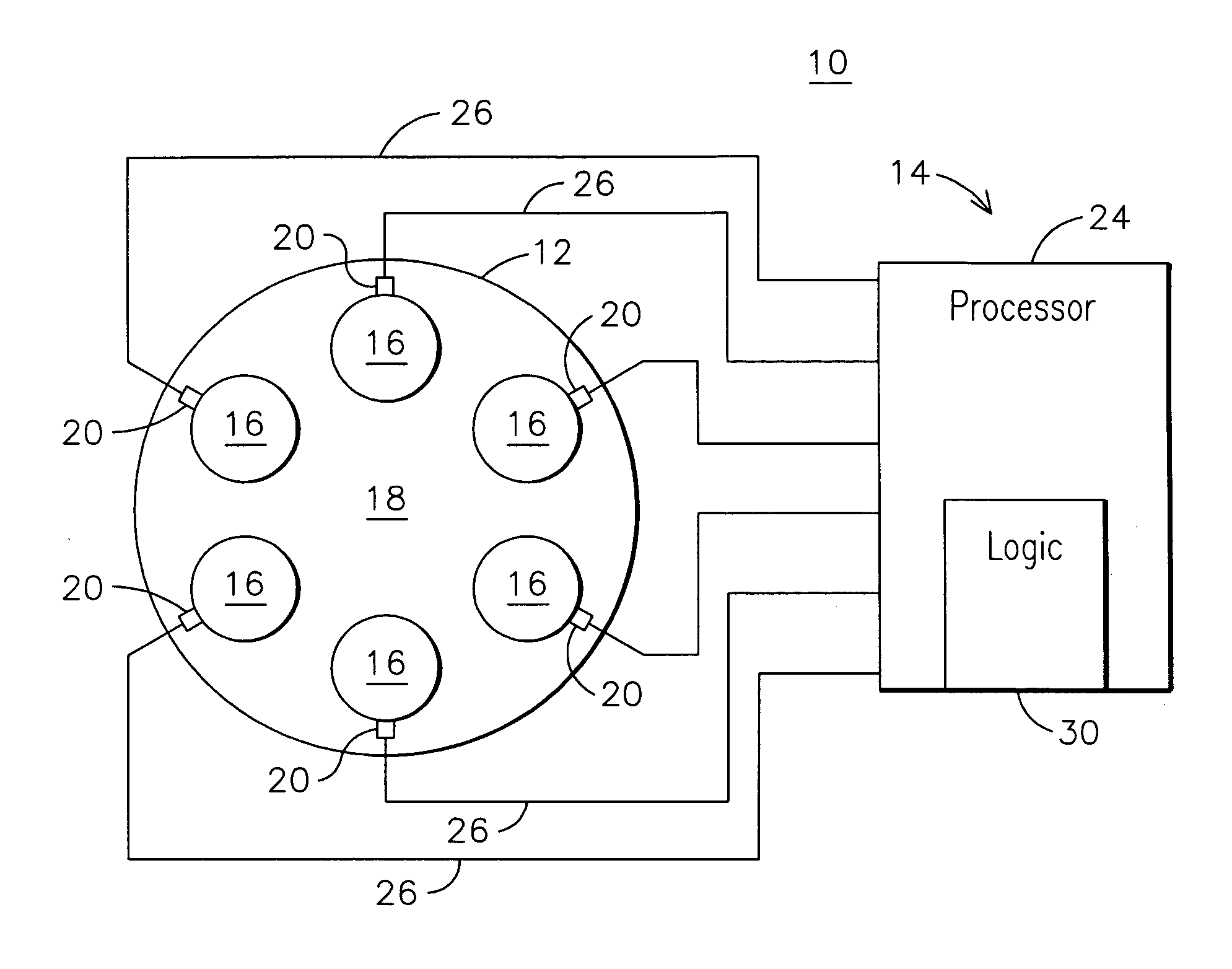
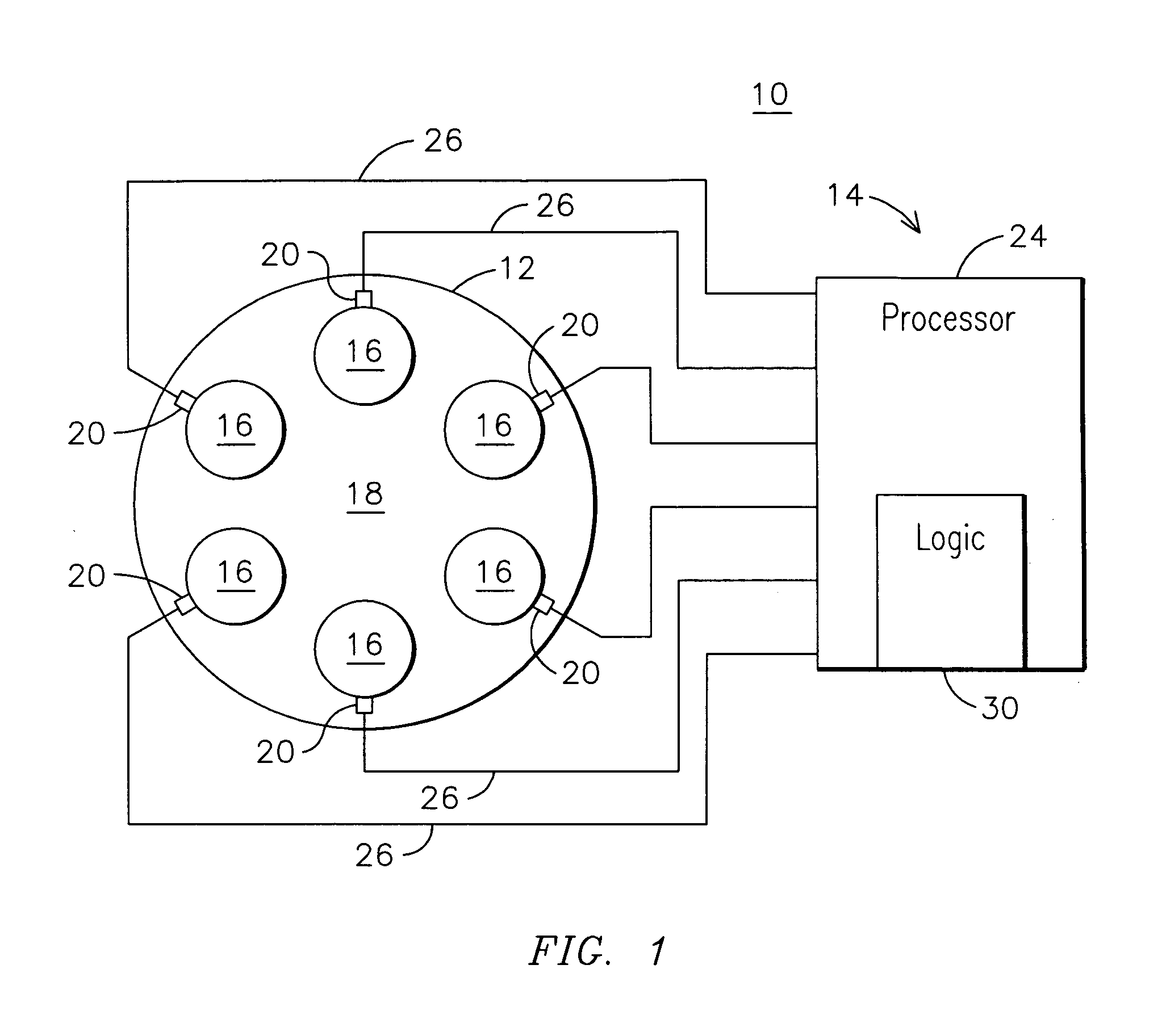
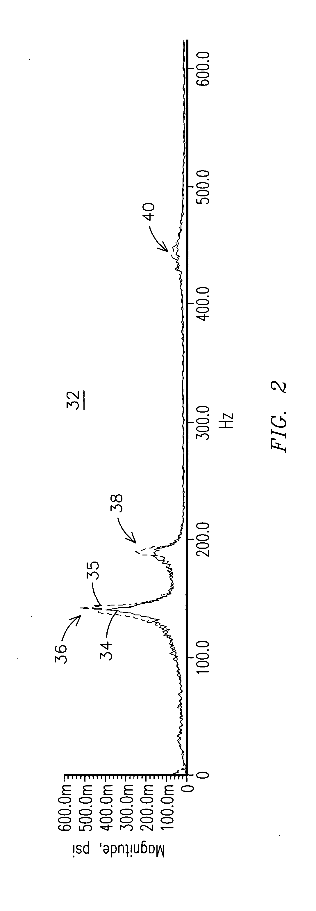
[0007] Individual cans of a can annular combustor of a gas turbine engine may exhibit amplitude spikes at certain acoustic frequencies during operation. FIG. 2 shows an example frequency spectrum 32 of Fourier-transformed acoustic waveform signa...


PUM


Abstract

A method for monitoring combustion dynamics of a can annular combustor (12) of a gas turbine engine includes monitoring respective dynamic operating conditions of cans (16) of the can annular combustor with respective dynamic operating condition sensors (20) associated with each of the cans. The method also includes grouping the cans into two or more groups according to their respective dynamic operating conditions and identifying a sensor providing an anomalous dynamic operating condition reading for at least one of the cans. The method further includes determining a need to service the identified sensor according to the associated can's group membership.

Description

FIELD OF THE INVENTION [0001] The invention relates to gas turbine engines, and more particularly, to monitoring combustion dynamics when one or more dynamic operating condition sensors provides an anomalous reading. BACKGROUND OF THE INVENTION [0002] Gas turbines engines having can-annular combustors are known wherein individual cans, including a combustion zone within the can, feed hot combustion gas into respective individual portions of an arc of a turbine inlet. The individual cans may receive fuel and air for combustion and be disposed in a ring around a central region of a combustor of the engine. Combustion generated dynamic pressure fluctuations, or combustion dynamics, produced in gas turbine engines, and especially in gas turbine engines having Dry, Low NOx (DLN) combustion systems, need to be carefully monitored and controlled to achieve acceptable system durability and reliability. As DLN combustion systems are increasingly required to be operated more aggressively with...

Claims


Application Information

Patent Timeline
IPC IPC(8): F02C1/00
CPCF05D2260/80F01D21/003
Inventor BLAND, ROBERTJOHNSON, CLIFFORD
Owner SIEMENS ENERGY INC
Why Eureka
Try Eureka