Pressure Detecting Apparatus Utilizing Electromagnetic Coupling

a technology of electromagnetic coupling and detecting apparatus, which is applied in the direction of instruments, pedestrian/occupant safety arrangements, force/torque/work measurement apparatus, etc., can solve the problems of difficult to make a large sensor, the detecting apparatus using pressure-sensitive rubber or electrostatic coupling is easily affected, and cannot be applied to a wide area. , to achieve the effect of less affected, large size and cheap production

Inactive Publication Date: 2007-09-20
XIROKU INC
View PDF11 Cites 12 Cited by
  • Summary
  • Abstract
  • Description
  • Claims
  • Application Information

AI Technical Summary

Benefits of technology

[0008] Taking the above-described problem into consideration, it is an object of the present invention to provide a pressure detecting apparatus that utilizes electromagnetic coupling to thereby enable it to have low impedance, to be less affected from noises and to be constructed in a large size.
[0026] The pressure detecting apparatus utilizing electromagnetic coupling according to the present invention has an advantage in that it can be made in a large size since it is less affected from noises. In addition, since the detection circuit has no complex configuration and the sensor section is constructed with coils, the pressure detecting apparatus can be produced cheaply even though it is made in a large size. Moreover, the sensor section made in the thin sheet form can be manufactured easily by employing a process tp form a coil pattern with flexible base plates or the like.

Problems solved by technology

As described above, although the sensor using a differential transformer can detect a part of pressure, it cannot be applied for detecting pressure distribution over a wide area.
Besides, the pressure detecting apparatuses using pressure-sensitive rubber or electrostatic coupling are easily affected by noises due to their relatively-high impedance, and it has been therefore difficult to make the sensor in a large size.
However, in such a case that, for example, the pressure detecting apparatuses are bedded over floors in a shop to investigate the movements of visitors or are used for security purpose, it has been difficult to determine the pressure distribution with the pressure detecting apparatuses since they receive too much effect of noises.

Method used


Image

  • Pressure Detecting Apparatus Utilizing Electromagnetic Coupling
  • Pressure Detecting Apparatus Utilizing Electromagnetic Coupling
  • Pressure Detecting Apparatus Utilizing Electromagnetic Coupling

Examples


Embodiment Construction

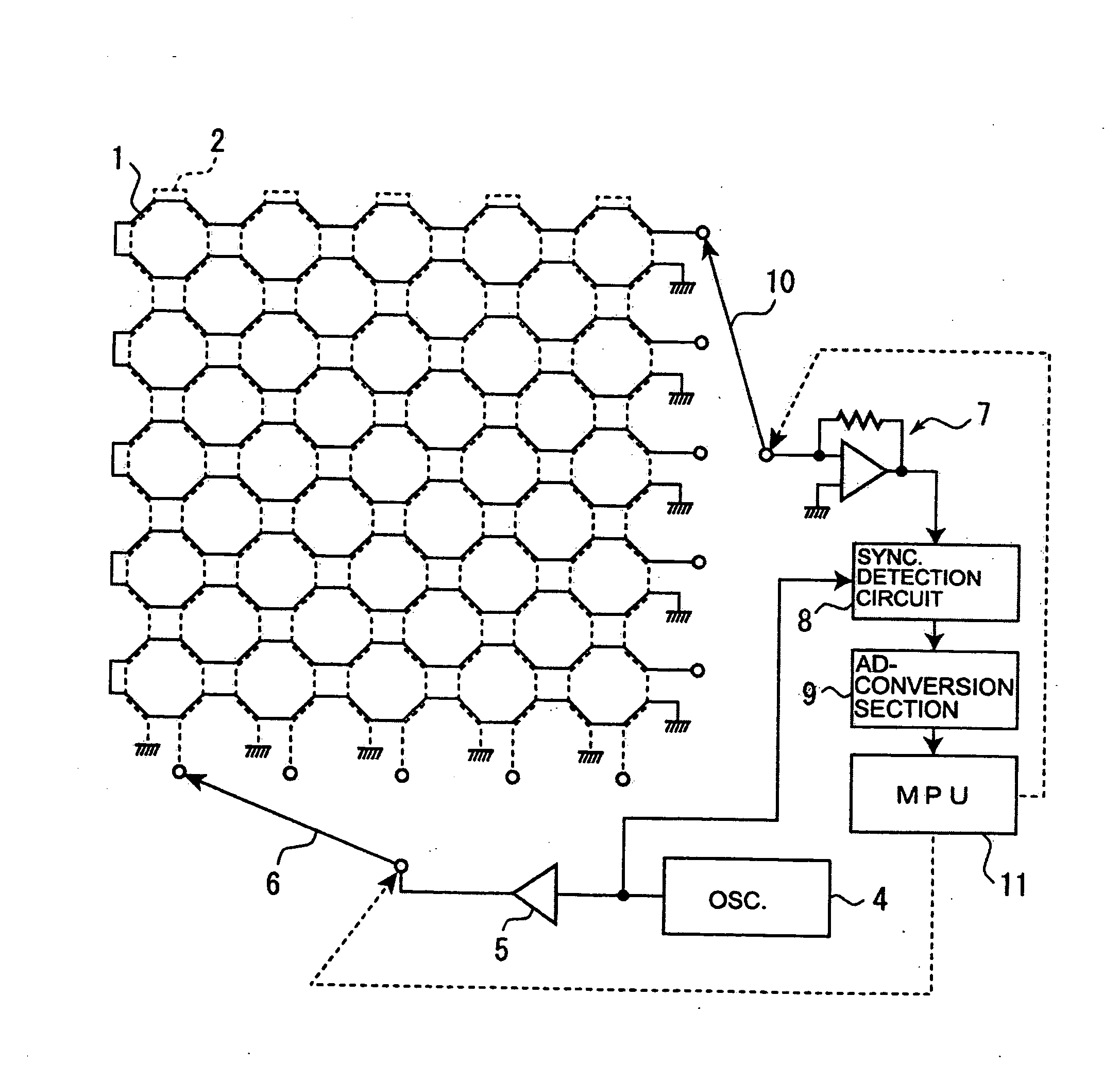
[0036] Now, the best mode for carrying out the present invention will be explained in the following with referring to the appended drawings. Note that, though a pressure detecting apparatus, in which coils are disposed in a matrix state in both directions of the X-axis and the Y-axis to capacitate the apparatus to determine the distribution of pressure will be explained in the following examples, it is not intended to limit the present invention to those examples. The pressure detecting apparatus according to this invention can naturally detect pressure by means of a set of sensors functioning as a minimal unit in such a case that it is not necessary to determine the distribution of pressure but is required to simply measure pressure.

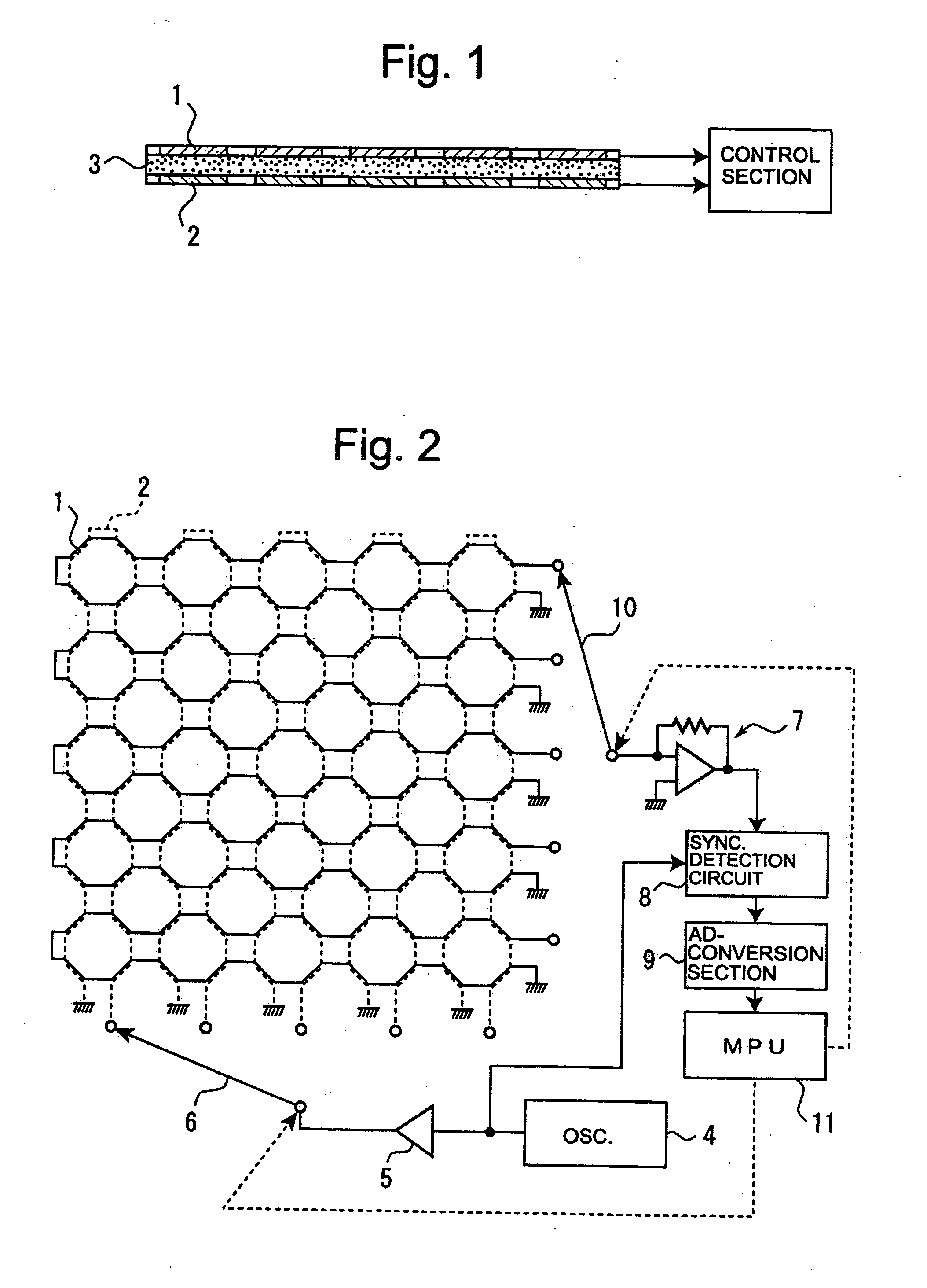
[0037]FIG. 1 is a schematic lateral cross-section for explaining the pressure detecting apparatus of Example 1 according to the present invention. FIG. 2 includes a schematic top view of the pressure detecting apparatus and a,block diagram of the drive...


PUM

PropertyMeasurementUnit
modulus of elasticityaaaaaaaaaa
pressureaaaaaaaaaa
magnetic fieldaaaaaaaaaa

Abstract

The object of the present invention is to provide a pressure detecting apparatus that is less affected from noises and can be constructed in a large size. The pressure detecting apparatus according to the present invention utilizes electromagnetic coupling. The sensor section comprises first coils 1, second coils 2 provided on the first coils such that they are superimposed to each other, and a first cushion member 3 provided between the first coils and the second coils. A drive circuit for driving either of the first coils and the second coils and a detection circuit for detecting pressure applied against the sensor section on the basis of signals resulting from electromagnetic coupling from the other of the first coils and the second coils are connected to the sensor section. The sensor sections are disposed in a matrix state so that measurements of pressure distribution can be effected.

Description

FIELD OF THE INVENTION [0001] The present invention relates to a pressure detecting apparatus, and particularly to a pressure detecting apparatus that utilizes electromagnetic coupling caused by coils. BACKGROUND OF THE INVENTION [0002] Till now, various apparatuses for measuring pressure applied by an object against a sensor section and an amount of displacement thereof have been developed. In JP Laid-open No. 9-113203, for example, a sensor using a differential transformer is disclosed. This sensor is designed to detect the relative amount of displacement between a core and a differential coil to thereby determine an amount of displacement of an object. Since each of the core and the differential coils has a thickness, respectively, it is difficult to comprise them in a thin sheet. Thus, it has been difficult to apply such a sensor to a pressure distribution detecting apparatus. [0003] There are various types of pressure distribution detecting apparatuses for detecting pressure di...

Claims


Application Information

Patent Timeline
Patent Type & Authority Applications(United States)
IPC IPC(8): G01L1/12G01L1/14B60R21/015G01L5/00
CPCG01L1/14B60R21/01516B60R21/01532G01L5/00
Inventor OGAWA, YASUJI
Owner XIROKU INC
Why Eureka
Try Eureka