Blast protection system

a protection system and blast technology, applied in the direction of protective equipment, weapons, armour, etc., can solve the problems of not being able to protect all vulnerable structures, potential targets may become targets, and the vulnerable of bridge columns, so as to minimize the amount of energy.

Inactive Publication Date: 2007-09-20
SWINSON JOHN S
View PDF10 Cites 11 Cited by
  • Summary
  • Abstract
  • Description
  • Claims
  • Application Information

AI Technical Summary

Benefits of technology

[0009] The blast protection system is positioned so as to abut or reside a short distance from the structure to be protected. The wall members are joined by welding, mechanical fasteners or similar means to create an extended or multi-directional perimeter, and are preferably secured to the ground surface by connecting mechanical fasteners to the footing members. The particulate matter is placed within the interior of the perimeter formed by the wall members. In the event that an explosive is detonated in close proximity to the blast protection system, the blast shock wave causes the folds of the wall to unfold and extend in an upward direction, thereby initiating a diversion of the blast energy away from the structure being protected. This upward motion is likewise transferred to at least a portion of the particulate matter, such that the horizontal energy of the blast is dissipated through absorption by the loose particles and diverted into a generally vertical direction by upward expulsion of the particles as well, thereby minimizing the amount of energy that impacts the structure directly.

Problems solved by technology

Many important buildings are now protected by exclusionary barriers that prevent a vehicle from being brought near the building, but it is not possible to protect all vulnerable structures in this manner due to economic and physical space considerations, as most buildings front on a public street open to all vehicular traffic.
In such a circumstance, providing an exclusionary safety buffer of sufficient area may be possible only by closing the street—an impractical solution.
In addition, buildings previously considered to be outside the list of potential targets may become targets if temporarily occupied by targeted personnel, such as is the case for example of buildings now occupied in Iraq by U.S. personnel.
Bridges columns are especially vulnerable as the columns are always positioned adjacent the roadway, and the columns are the sole supports for the roadway.
Destruction of bridges disrupts vehicular travel and may simultaneously block waterways or ports.
Detonation of an explosive produces a shock wave of dramatically increased pressure and thermal energy, which if unmitigated is often sufficient to cause massive destruction of fixed structures within effective range of the explosion.
If directed at a vulnerable area of a tall or large structure, such as a high-rise tower or a suspension bridge, the direct blast damage may instigate indirect structural failure of a magnitude sufficient to destroy the entire structure through collapse.

Method used


Image

  • Blast protection system
  • Blast protection system
  • Blast protection system

Examples


Embodiment Construction

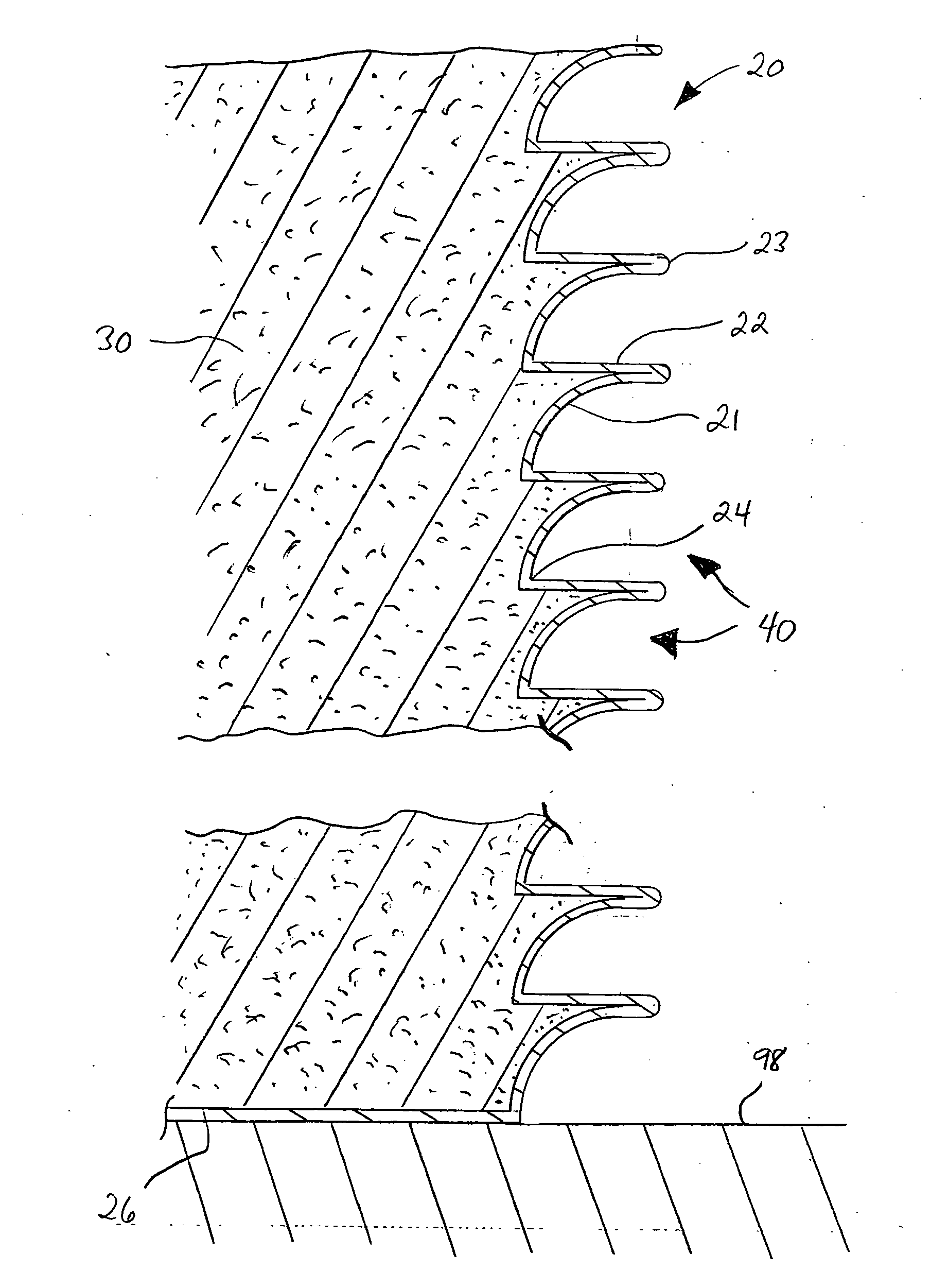
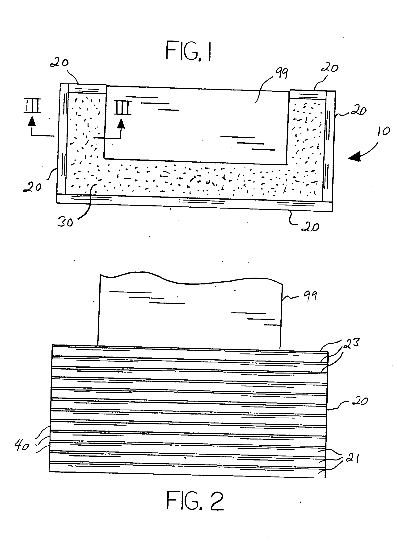
[0018] With reference to the drawings, the invention will now be described in detail with regard for the best mode and the preferred embodiment. In general, the invention is a blast protection barrier system 10 comprising horizontally folded wall members 20 and energy dissipating particulate matter 30 used to protect a structure 99 from a blast shock wave resulting from detonation of an explosive adjacent the blast protection system 10. The system 10 will typically comprise multiple linear wall members 20 joined as required to shield the structure 99 from multiple directions by forming a perimeter. The protected structures 99 may consist of buildings, towers, storage tanks, or any other structure or object requiring protection of the type described herein. For purposes of illustration, the invention is herein shown as protecting the three sides of a bridge column facing a roadway, but it is to be understood that the invention may be constructed to face any number of directions and m...


PUM

PropertyMeasurementUnit
angleaaaaaaaaaa
centered radiusaaaaaaaaaa

Abstract

A blast protection barrier system to protect structures from blast shock waves initiated by detonation of a large bomb at ground level adjacent the structure, and in particular a bomb transported by a land vehicle, having an outer perimeter wall retaining a large quantity of loose particulate matter, the wall having multiple horizontally extending folds, each fold having an outwardly facing inclined, preferably concave, segment joined to a generally horizontal segment, such that the blast shock wave causes the wall to extend or expand in a generally vertical direction to dissipate and divert the destructive energy of the bomb and minimize damage to the structure.

Description

BACKGROUND OF THE INVENTION [0001] The invention relates most generally to devices, structures, apparatuses and systems designed to protect structures from explosive blast effects, and more particularly to such devices, etc., that are designed to protect against explosions from large bombs detonated adjacent the structure being protected. Even more particularly, the invention relates to such devices, etc., that incorporate protective barriers erected externally to or adjacent the structure being protected. [0002] An increasingly common terrorist tactic is the detonation of large portable bombs, usually transported within a car or truck, to destroy or severely damage large buildings or similar fixed structures. Delivering the bombs to the target can be relatively easy, as the transport vehicle is simply driven to a location adjacent the building and the explosives are detonated. Many important buildings are now protected by exclusionary barriers that prevent a vehicle from being brou...

Claims


Application Information

Patent Timeline
Patent Type & Authority Applications(United States)
IPC IPC(8): F41H5/04F41H5/02F41H5/24
CPCE04H9/10F41H5/24F41H5/0457
Inventor SWINSON, JOHN S.
Owner SWINSON JOHN S
Why Eureka
Try Eureka