Method and Apparatus for Securely Storing Medical Items Within a Thermal Treatment System

Active Publication Date: 2007-09-20
MEDICAL SOLUTIONS +1
View PDF100 Cites 69 Cited by
  • Summary
  • Abstract
  • Description
  • Claims
  • Application Information

AI Technical Summary

Benefits of technology

[0008] Accordingly, the present invention embodiments employ a locking mechanism for thermal treatment systems (e.g., systems heating and/or cooling solutions prior to the solutions being administered to the patient) or other medical equipment to secure medications being stored and/or thermally treated therein. T

Problems solved by technology

For example, some fluids, such as whole blood or fluids containing medication, should be warmed evenly to a specific temperature and can be rendered unusable or

Method used


Image

  • Method and Apparatus for Securely Storing Medical Items Within a Thermal Treatment System
  • Method and Apparatus for Securely Storing Medical Items Within a Thermal Treatment System
  • Method and Apparatus for Securely Storing Medical Items Within a Thermal Treatment System

Examples


Embodiment Construction

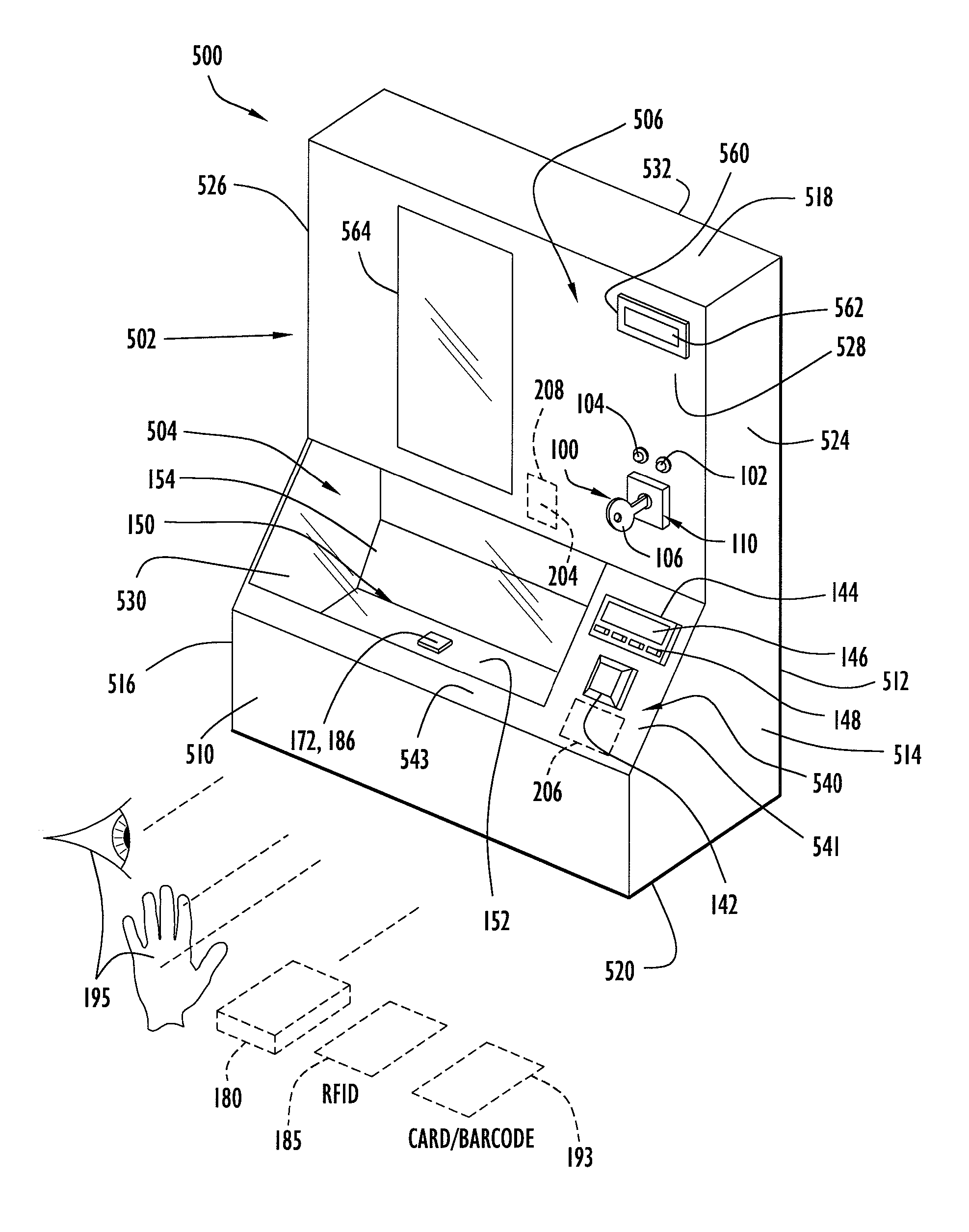
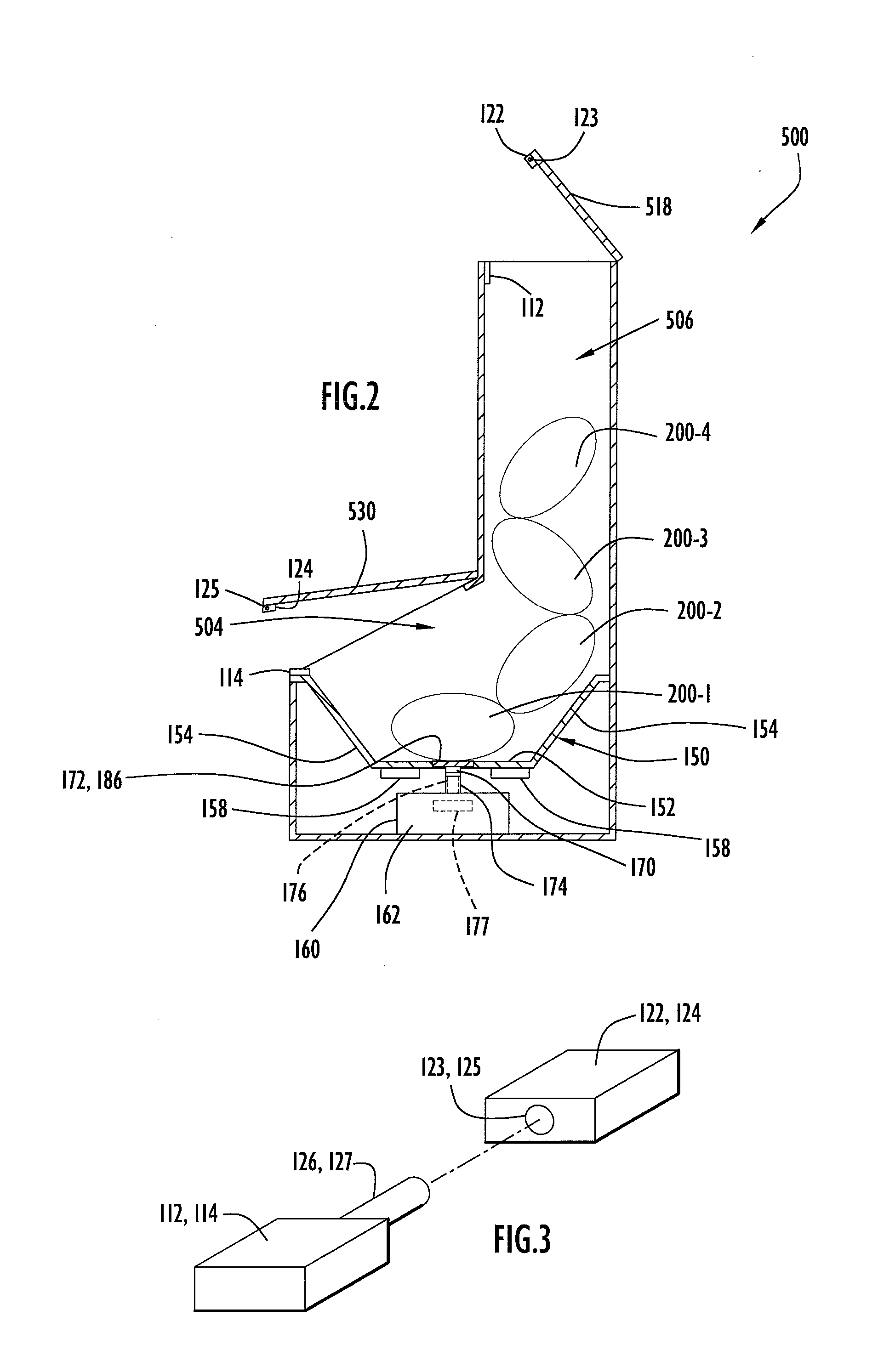
[0015] An exemplary thermal treatment system employing the locking mechanism of a present invention embodiment is illustrated in FIGS. 1-2. Initially, the system is of the types disclosed in aforementioned U.S. Pat. No. 6,768,085 (Faries, Jr. et al.) and U.S. Pat. No. 7,041,941 (Faries, Jr. et al.). Specifically, system 500 includes a housing 502 including a heating compartment 504 and a storage compartment 506 disposed above the heating compartment. The heating compartment includes a front wall 510, a rear wall 512, side walls 514, 516, a bottom wall 520 and a front panel 540 that collectively define the heating compartment interior. A door 530 is disposed on the housing to cover a heating compartment open portion that facilitates placement and removal of items within the heating compartment as described below. Front and rear walls 510, 512 are substantially rectangular and are attached to and extend between side walls 514, 516. Front wall 510 has a height substantially less than t...


PUM


Abstract

A locking mechanism for thermal treatment systems (e.g., systems heating and/or cooling solutions prior to the solutions being administered to the patient) or other medical equipment according to the present invention embodiments secures medications being stored and/or thermally treated therein. The locking mechanism includes an integrated monitoring and display system to determine and indicate the status of the thermal treatment system. The monitoring and display system includes indicator lights that allow for a visual representation indicating the locked or open states of system access doors and/or an audio system or alarm for alerting medial or other personnel to the status of the locking mechanism.

Description

CROSS-REFERENCE TO RELATED APPLICATIONS [0001] This application claims priority from U.S. Provisional Patent Application Ser. No. 60 / 783,389, entitled “Method and Apparatus for Securely Storing Medical Items Within a Thermal Treatment System” and filed Mar. 20, 2006, the disclosure of which is incorporated herein by reference in its entirety.BACKGROUND OF THE INVENTION [0002] 1. Technical Field [0003] The present invention embodiments pertain to systems for thermally treating medical items, such as the types of systems disclosed in U.S. Pat. No. 5,408,576 (Bishop), U.S. Pat. No. 6,259,067 (Faries, Jr. et al.), U.S. Pat. No. 6,294,762 (Faries, Jr. et al.), U.S. Pat. No. 6,376,805 (Faries, Jr. et al.), U.S. Pat. No. 6,384,380 (Faries, Jr. et al.), U.S. Pat. No. 6,467,953 (Faries, Jr. et al.), U.S. Pat. No. 6,566,631 (Faries, Jr. et al.), U.S. Pat. No. 6,640,974 (Faries, Jr. et al.), U.S. Pat. No. 6,722,782 (Faries, Jr. et al.), U.S. Pat. No. 6,768,805 (Faries, Jr. et al.) and U.S. Pat...

Claims


Application Information

Patent Timeline
IPC IPC(8): E05G1/00
CPCA61B19/0248A61B19/026A61B2017/00084A61B2019/0249E05B47/026A61M5/44E05B41/00E05B47/0002A61B2019/0298A61B50/10A61B50/30A61B2050/0018A61B2050/105
Inventor FARIES, DURWARD I. JR.HEYMANN, BRUCE R.HENDRIX, DAVID
Owner MEDICAL SOLUTIONS
Why Eureka
Try Eureka