Al technical title is built by PatSnap Al team. It summarizes the technical point description of the patent document.
a flow stabilizer and pipe technology, applied in the direction of liquid transfer devices, instruments, lighting and heating apparatus, etc., can solve the problems of insufficient space for this length of pipe run, problems such as disappearance or diminishmen
Inactive Publication Date: 2007-09-20
METRAFLEX
View PDF53 Cites 3 Cited by
Summary
Abstract
Description
Claims
Application Information
AI Technical Summary
This helps you quickly interpret patents by identifying the three key elements:
Problems solved by technology
Method used
Benefits of technology
[0009] A connecting segment of pipe is provided with a flow straightening device which significantly reduces the required length of pipe between the source of the turbulence, such as a pump, and the fluid control device, such as a valve. The connecting segment may be provided with other features, such as shock or vibration absorption, misalignment compensation, or fastener conversion elements.
Problems solved by technology
Frictional losses and other problems develop as a result of turbulent flow, which problems disappear or diminish as flow becomes more laminar.
Oftentimes the space for this length of pipe run is not available.
Method used
Image
Click on the blue label to locate the original text in one second.
Reading with bidirectional positioning of images and text.
Examples
Embodiment Construction
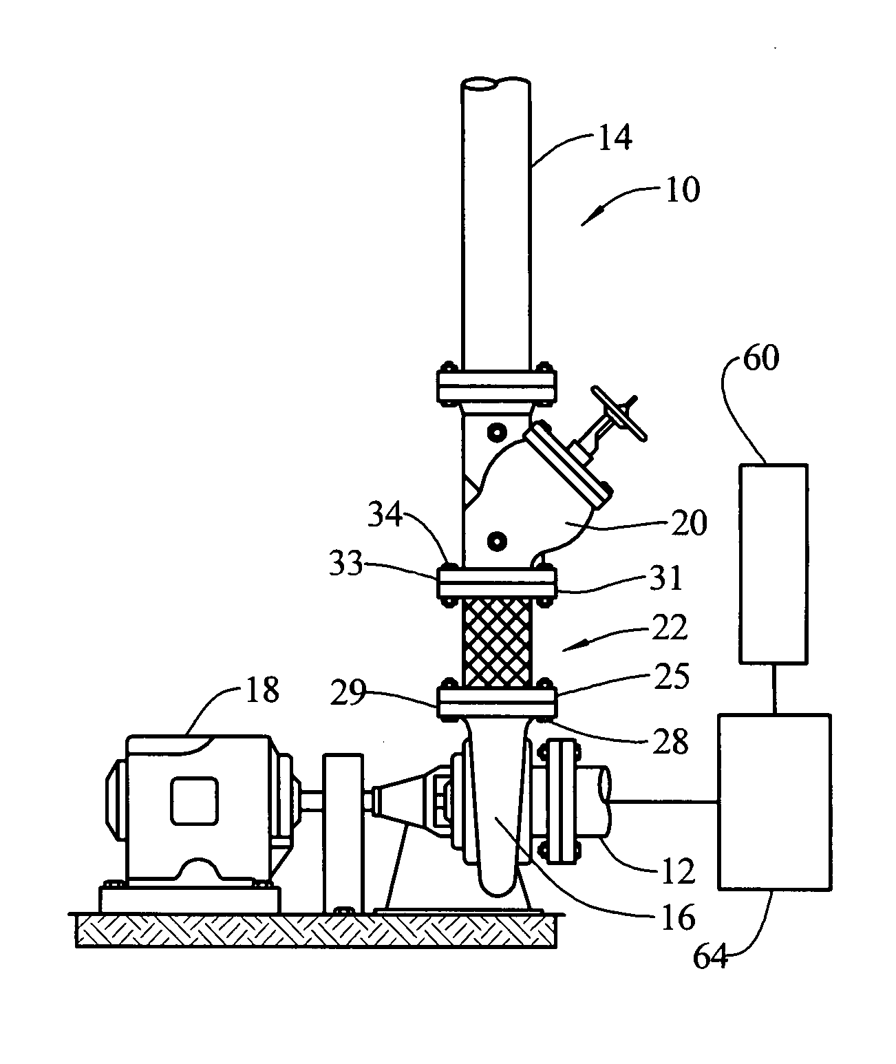
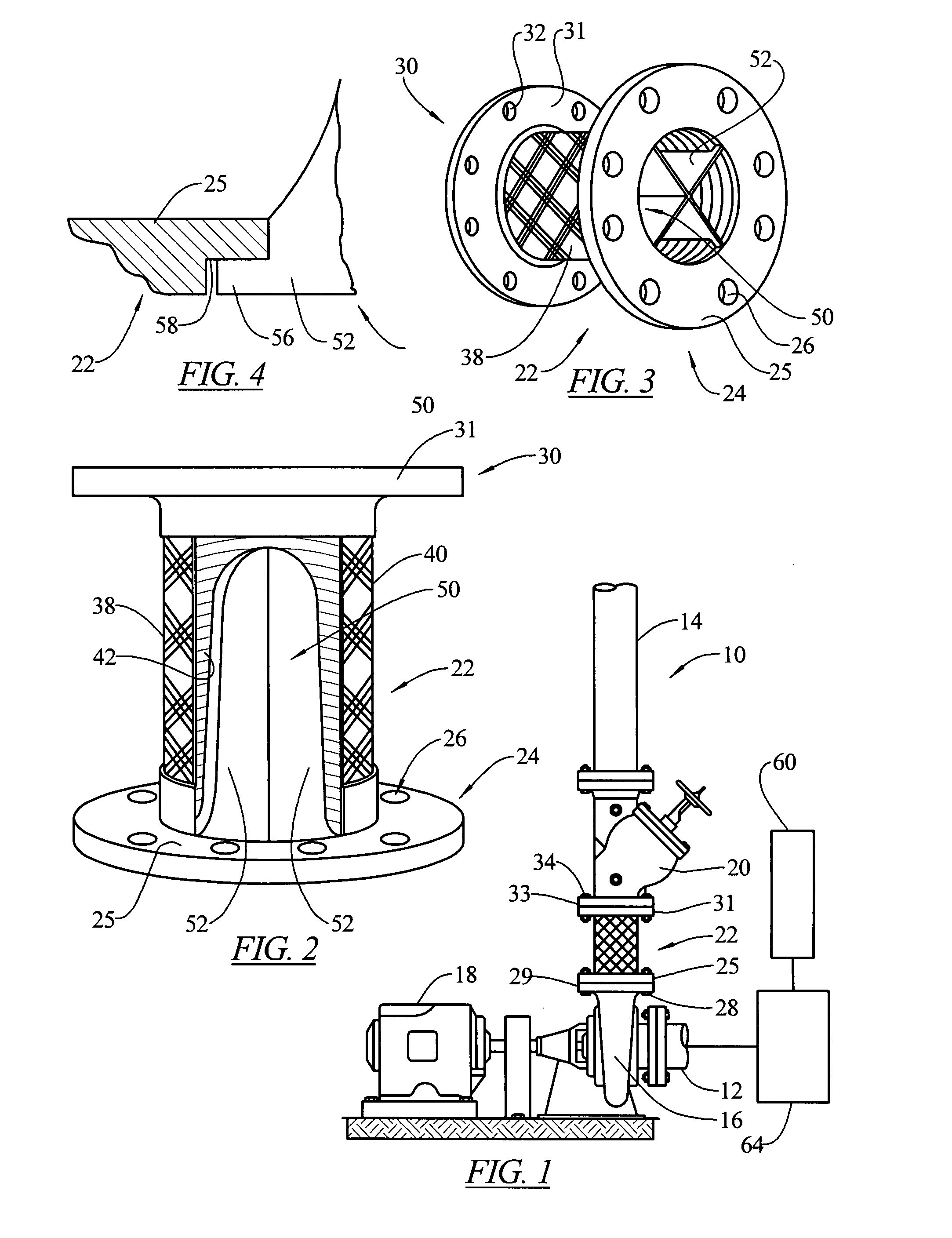
[0022] The present invention provides a device arranged to stabilize a fluid flow in an enclosed space, such as in a pipe line or other fluid conduit. Although the present invention is not limited only to pipelines, as an illustrative embodiment of the invention, it is shown in such an arrangement.
[0023] In FIG. 1 a conduit in the form of a pipeline is illustrated generally at 10 and includes an upstream pipe portion 12 and a downstream pipe portion 14 arranged for carrying fluids in the downstream direction and interposed between the two pipe sections are a series of elements which act on the fluid flow. Specifically, a turbulence creating device, such as a pump 16 which may be driven by a motor 18 is used to draw in fluid from the inlet pipe section 12 and to drive that fluid toward the downstream pipe section 14. As a result of the action of the pump, which may incorporate moving internal components such as vanes, rotors, diaphragms, etc. as is well known in the art, turbulence ...
PUM
Abstract
A fluid flow stabilizer for use in a flow of fluid in a conduit between a source of turbulence and a fluid control device. The stabilizer comprises a fluid conduit section having a first end with a mounting arrangement for mounting the first end to the fluid conduit and a second end with a mounting arrangement for mounting the second end to the fluid conduit, the fluid conduit section having a fluid passage therethrough to allow fluid to flow from the first end to the second end, and a flow straightening device positioned in the fluid conduit section. The fluid conduit section may be constructed to absorb at least one of shock, vibration and alignment in the conduit.
Description
FIELD OF THE INVENTION [0001] The present invention relates to flow stabilizers and more particularly to flow stabilizers for use in pipes. BACKGROUND OF THE INVENTION [0002] A known characteristic of fluid flow, such as the flow of liquid in a pipe, is the turbulence of the flow. Turbulence in a pipeline can be created by bends in the pipe run, connections with other pipes, partially opened valves, constrictions in the pipe, as well as moving mechanical devices such as the moving elements of a pump such as a pump rotor, diaphragm, vanes, etc. [0003] Frictional losses and other problems develop as a result of turbulent flow, which problems disappear or diminish as flow becomes more laminar. There are known devices used to reduce turbulence in a fluid flow such as the flow straightening devices shown in U.S. Pat. Nos. Re. 31,258; 3,946,650; 2,929,248; 3,113,593; 3,840,051; 5,307,830; 5,309,946; 5,495,872; 5,762,107; 6,065,498; and 6,145,544. [0004] Devices such as those disclosed in ...
Claims
Application Information
Patent Timeline
Application Date:The date an application was filed.
Publication Date:The date a patent or application was officially published.
First Publication Date:The earliest publication date of a patent with the same application number.
Issue Date:Publication date of the patent grant document.
PCT Entry Date:The Entry date of PCT National Phase.
Estimated Expiry Date:The statutory expiry date of a patent right according to the Patent Law, and it is the longest term of protection that the patent right can achieve without the termination of the patent right due to other reasons(Term extension factor has been taken into account ).
Invalid Date:Actual expiry date is based on effective date or publication date of legal transaction data of invalid patent.
Patent Type & Authority Applications(United States)