Testing device and testing unit

a testing device and engine technology, applied in engine testing, structural/machine measurement, instruments, etc., can solve the problem of limit in reducing pipeline length, and achieve the effect of reducing pipeline length

Inactive Publication Date: 2015-10-01
HIRATA & CO LTD
View PDF0 Cites 3 Cited by
  • Summary
  • Abstract
  • Description
  • Claims
  • Application Information

AI Technical Summary

Benefits of technology

[0008]The present invention has an object to realize automation of opening / closing of the valve and to further reduce the pipeline length.

Problems solved by technology

However, the valve with actuator requires an arrangement space for an actuator and has limitation in reduction of the pipeline length.

Method used


Image

  • Testing device and testing unit
  • Testing device and testing unit
  • Testing device and testing unit

Examples


Embodiment Construction

[0020]An embodiment of the present invention will be described below. In each figure, an arrow Z indicates a vertical direction, and arrows X and Y indicate horizontal directions orthogonal to each other.

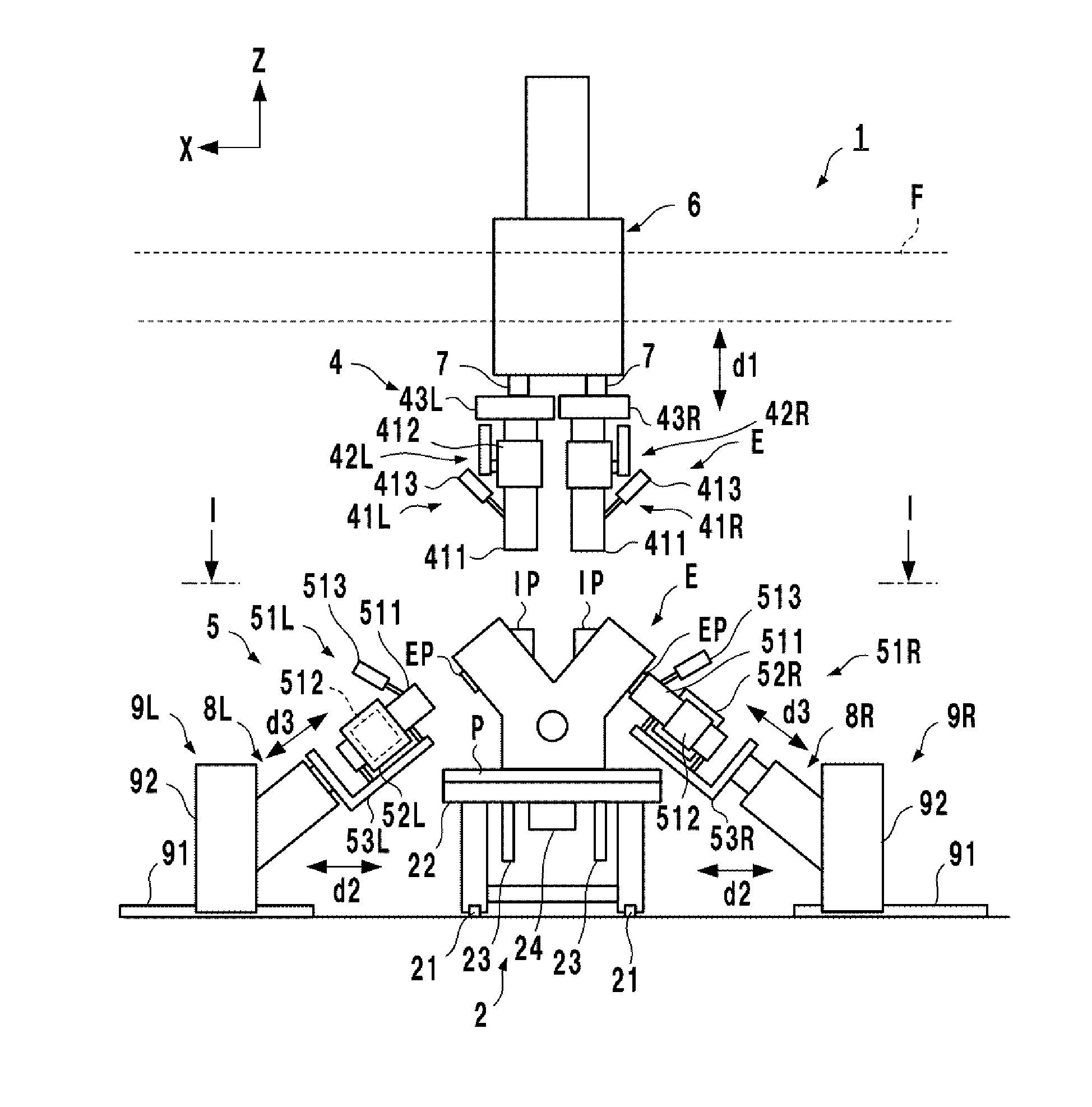
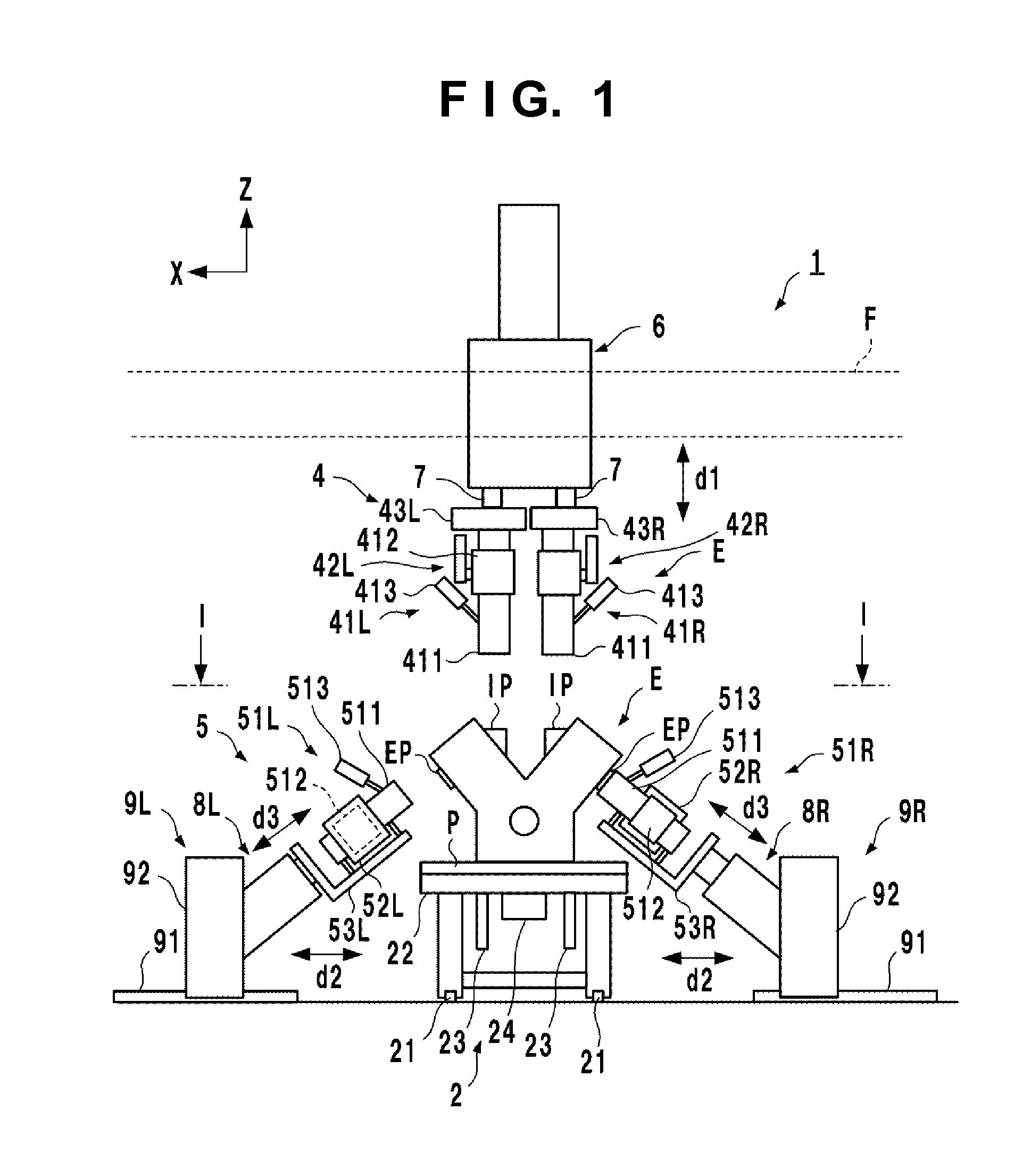
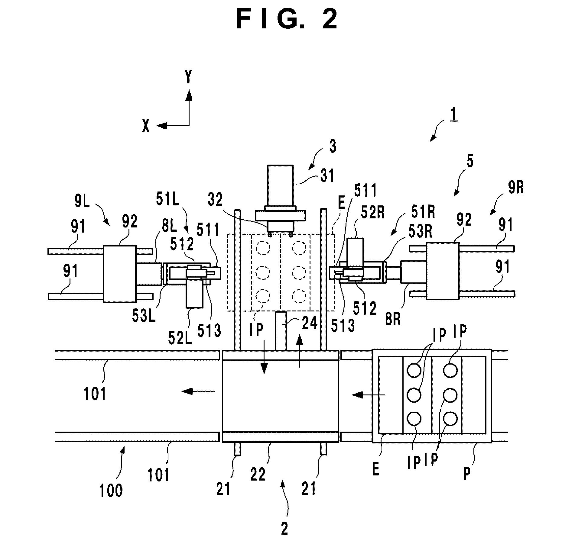
[0021]FIG. 1 is a schematic view of a testing device 1 according to an embodiment of the present invention, and FIG. 2 is an I-I line arrow view of FIG. 1. Assuming that FIG. 1 is a front view of the testing device 1, FIG. 2 corresponds to a plan view excluding a part of the configuration of the testing device 1. In FIG. 1, a specific configuration of a conveying device 100 is omitted.

[0022]The testing device 1 takes in an engine E conveyed in an X-direction by the conveying device 100 which may be a roller conveyer or the like, conducts a test and returns the engine E to the conveying device 100 again after the test. The test conducted by the testing device 1 for the engine E is a test conducted in a pseudo driving state without combustion of fuel, and this is a device for conducti...


PUM


Abstract

The present invention provides a testing device testing a multi-cylinder engine including a plurality of ports including an intake port and an exhaust port in a pseudo driving state. The device includes a plurality of pressure inspection units and at least one opening/closing mechanism. Each of the plurality of pressure inspection units includes a pipeline connected to one of the plurality of ports, a sensor for detecting a pressure in the pipeline and a valve for opening/closing the pipeline. The opening/closing mechanism includes one actuator and a transmission mechanism connected to the actuator and transmitting a driving force of the actuator to an operation unit of each of the plurality of valves to open and close the plurality of valves.

Description

BACKGROUND OF THE INVENTION[0001]1. Field of the Invention[0002]The present invention relates to a testing device and a testing unit of an engine.[0003]2. Description of the Related Art[0004]A device for conducting a test without combustion of fuel is proposed as a testing device of an engine. Japanese Patent No. 4315957, for example, discloses a device for measuring pressure fluctuation of an intake port or an exhaust port by rotating a crank shaft by an electric motor.[0005]A unit for measuring pressure fluctuation of the intake port and the exhaust port is generally provided with a pipeline connected to the ports, a sensor for detecting a pressure inside the pipeline, and a pipeline valve for opening / closing the pipeline. As a test example, there is a test for checking whether or not responsiveness of the intake / exhaust valve is within a reference value in an overlap zone of the intake / exhaust valve, for example. In this case, a pipeline on an intake side is opened, while the pip...

Claims


Application Information

Patent Timeline
Patent Type & Authority Applications(United States)
IPC IPC(8): G01M15/09G01M15/05G01M15/10
CPCG01M15/09G01M15/05G01M15/106G01M15/08
Inventor SUEOKA, HISAYUKIUCHIDA, TSUYOSHI
Owner HIRATA & CO LTD
Why Eureka
Try Eureka