Container skid-mounted compression hydrogenation device

A hydrogen refueling device and container technology, applied in the field of hydrogen refueling stations, can solve the problems of long installation and commissioning period, high land cost, and long station construction period, and achieve the effects of reducing the risk of hydrogen leakage, occupying a small area, and saving station construction costs

Active Publication Date: 2020-08-04
ZHANGJIAGANG FURUI HYDROGEN ENERGY EQUIP CO LTD +1
View PDF8 Cites 3 Cited by
  • Summary
  • Abstract
  • Description
  • Claims
  • Application Information

AI Technical Summary

Problems solved by technology

At present, most of the hydrogen refueling stations under construction and in operation in China are 35MPa fixed hydrogen refueling stations. These 35MPa fixed hydrogen refueling stations have complex structures, long construction period, large floor area, high land cost, long installation and commissioning period, Disadvantages such as low filling efficiency

Method used


Image

  • Container skid-mounted compression hydrogenation device
  • Container skid-mounted compression hydrogenation device
  • Container skid-mounted compression hydrogenation device

Examples


Embodiment 1

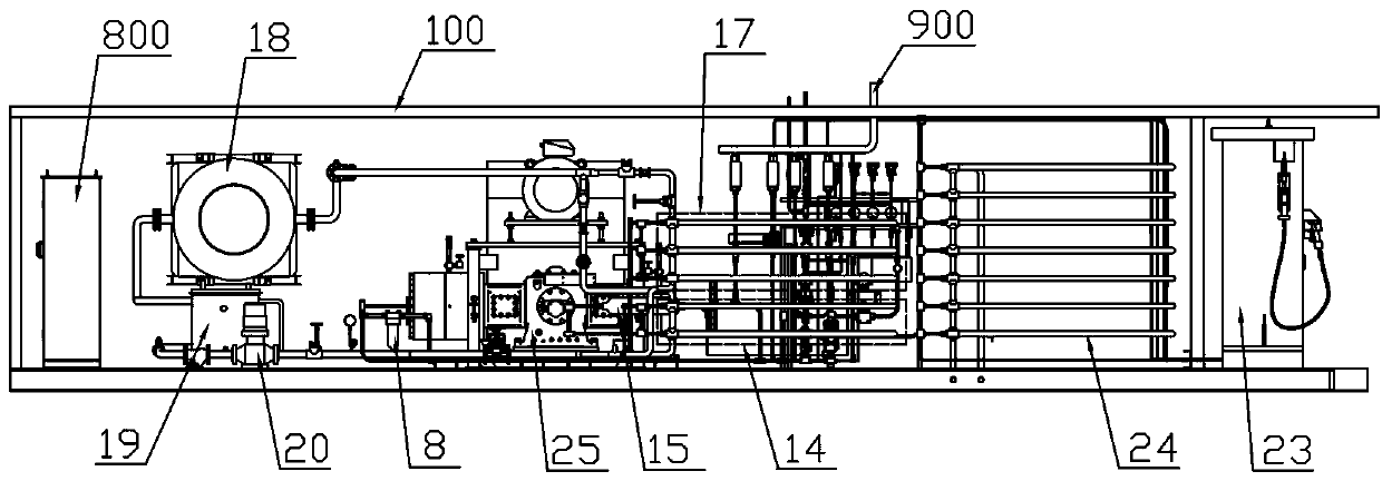
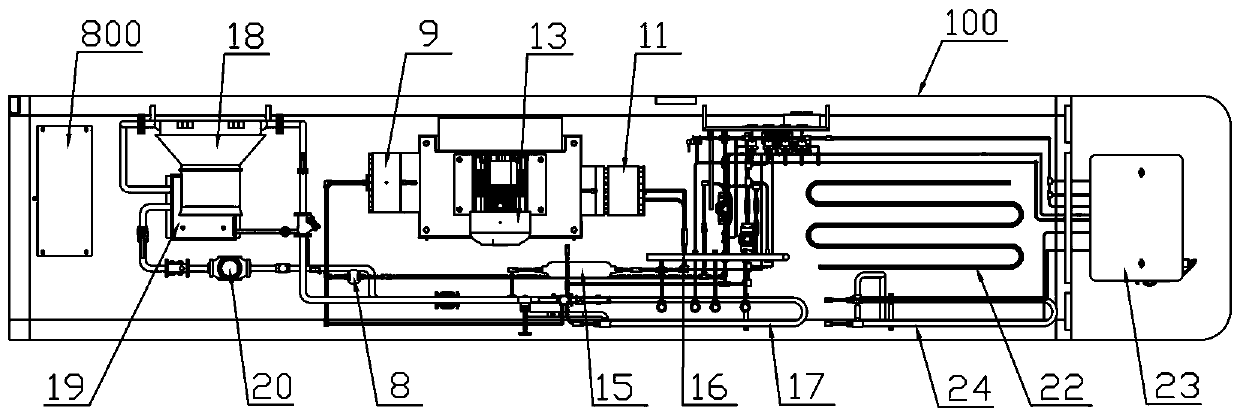
[0045] Such as figure 1 , figure 2 with Figure 15 As shown, a container skid-mounted compression hydrogenation device described in this embodiment includes: a container frame 100, the container frame 100 is composed of a top frame 101, a bottom frame 102, a front side frame 103, a rear side frame 104, a left The side frame 105 and the right side frame 106 encircle to form a rectangular parallelepiped frame structure.

[0046] Such as figure 1 , figure 2 with Figure 13 As shown, the compressor integrated frame 25 is fixedly installed in the container frame 100 and is located in the middle part of the bottom frame 102. In the compressor integrated frame 25, a motor 13, a primary compressor 9 with a leakage detection device 10 and a first-stage compressor with a leakage detection device 10 are fixedly arranged. The secondary compressor 11 of 12, the motor 13 is installed in the middle part of the upper layer of the compressor integrated frame 25, the primary compressor 9...

Embodiment 2

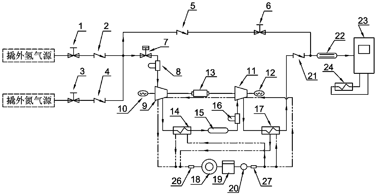
[0073] This embodiment is further improved on the basis of embodiment one, as Image 6 As shown, in this embodiment, one end of the second purge pipeline 506 is connected to the side wall of the first purge pipeline between the inlet of the first purge pipeline and the fourth check valve 5, and communicates with the first purge pipeline 505, Or one end of the second purge pipeline 506 is connected to the side wall of the main purge pipeline and communicated with the main purge pipeline 504 . The other end of the second purge pipeline 506 is connected to the side wall of the third hydrogen pipeline between the second check valve 21 and the buffer coil 22, communicated with the third hydrogen pipeline 503, or the other end of the second purge pipeline 506 is connected to On the first purge pipeline 505 between the second normally closed valve 6 and the outlet of the first purge pipeline; on the second purge pipeline 505 are provided a pressure regulator 38 and a third pneumatic ...

Embodiment 3

[0090] Such as Figure 15 , Figure 16 with Figure 17 As shown, several exhaust fans are fixedly installed on the top frame 101 of the container frame 100 through corresponding exhaust fan bases 201 at intervals, and several detachable sealing plates 202 and several first fixed sealing plates 203 cover the surface of the top frame 101, A number of rolling doors 204, a number of second fixed sealing plates 205, and a number of shutters 206 cover the side frames of the four sides of the container frame 100, thereby enclosing the top surface and the four sides of the entire container frame 100, thus protecting the container frame. Each component in 100 can prevent it from being affected by external environments such as dust and rain, and can ensure its ventilation and heat dissipation performance through a number of exhaust fans and a number of louvers 206, so as to avoid the accumulation of leaked hydrogen in the container frame 100 and cause potential safety hazards.

[0091...


PUM


Abstract

The invention discloses a container skid-mounted compression hydrogenation device. A container integration framework is fixedly installed in the middle part of a bottom frame of a container frame, a motor is located in the middle of the upper layer of the container integration framework, a primary compressor and a secondary compressor are arranged side by side on the lower layer of the container integration framework and arranged in a manner of front-and-back symmetry relative to the motor, and the primary compressor and the secondary compressor are driven by the motor. A water tank, a water pump, an air cooler and an electric control cabinet are fixedly arranged on the bottom frame behind the container integration framework. A first heat exchanger, a second heat exchanger, a third heat exchanger, a buffer coil pipe and a hydrogenator are arranged on the bottom frame in the front of the container integration framework, the first heat exchanger and the second heat exchanger are distributed in an up-and-down manner, and the third heat exchanger and the buffer coil pipe are arranged in the left-and-right direction. A buffer tank, a gas pipeline system and a cooling pipeline system arearranged at the space positions of the container integration framework. The container skid-mounted compression hydrogenation device is simple and compact in structure, the overall layout is balancedin the front-and-back direction, and the center of gravity is centered.

Description

technical field [0001] The invention relates to the technical field of hydrogenation stations, in particular to a container skid-mounted compression hydrogenation device. Background technique [0002] As a sustainable energy source, hydrogen energy can provide reliable, clean and low-cost electricity, which is the key to the sustainable development of transportation, transportation, industrial manufacturing and other industries. Hydrogen energy can bring huge benefits to energy, economy and environment, so the hydrogen energy economy is an inevitable solution for the successful energy transition. As a necessary link in the supply of hydrogen energy, hydrogen energy storage and transportation has attracted much attention. [0003] Hydrogen refueling stations are to fuel cell vehicles, just like gas stations are to traditional fuel vehicles, and charging piles are to pure electric vehicles. They are an indispensable cornerstone to support the development of the fuel cell vehi...

Claims


Application Information

Patent Timeline
Patent Type & Authority Applications(China)
IPC IPC(8): F17D1/04F17D1/07F17D1/065F17D3/01F17D3/03F17D5/00F17C7/00F17C13/00
CPCF17D1/04F17D1/07F17D1/065F17D3/01F17D3/03F17D5/00F17C7/00F17C13/00F17C2221/012F17C2221/014F17C2225/0123F17C2227/0157F17C2227/0348F17C2227/039F17C2205/0352Y02E60/32
Inventor 赵亚丽惠昱轩何春辉况开锋施海涛杜海滨陈甲楠苏红艳周佳琪
Owner ZHANGJIAGANG FURUI HYDROGEN ENERGY EQUIP CO LTD
Why Eureka
Try Eureka