

Vibration-Insulation Fasteners for Elongated Components
a technology of vibration insulation and elongated components, which is applied in the field of vibration insulation fasteners for elongated components, can solve the problems of reducing the ability of the fastener to maintain elongated components securely, increasing complexity in manufacture and use, and insufficient vibration damping, etc., to achieve adequate vibration damping, easy to manufacture, and convenient use
- Summary
- Abstract
- Description
- Claims
- Application Information
AI Technical Summary
Benefits of technology
Problems solved by technology
Method used
Image

Examples
first embodiment
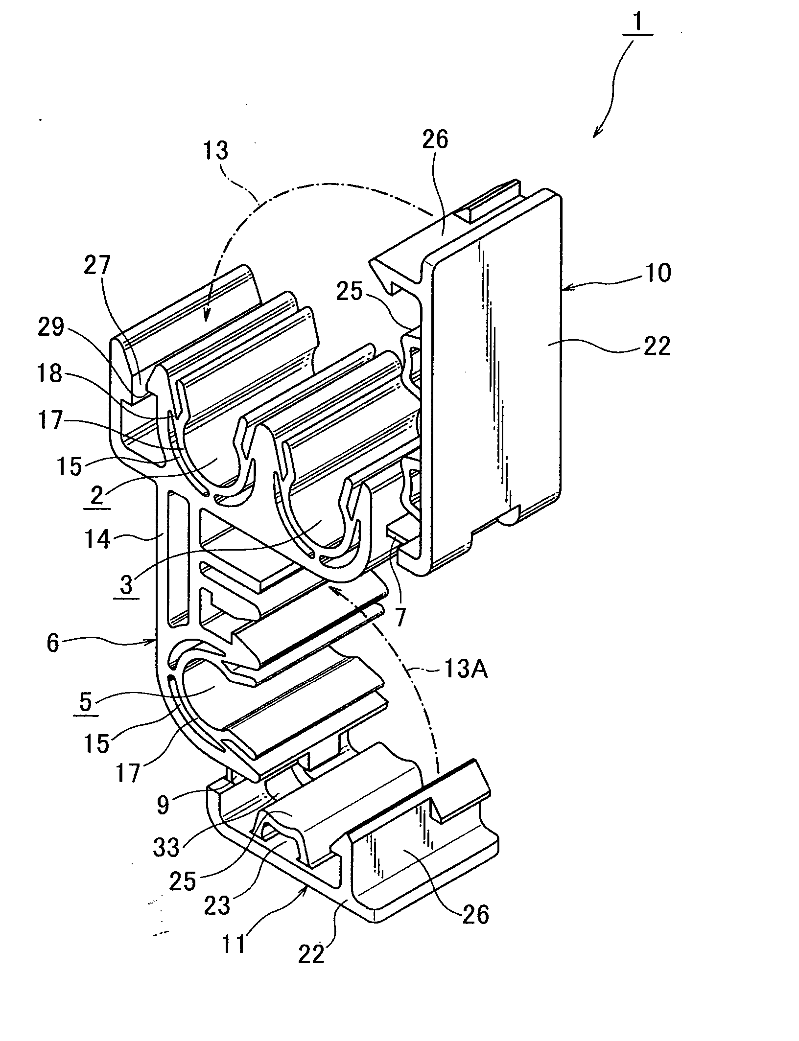
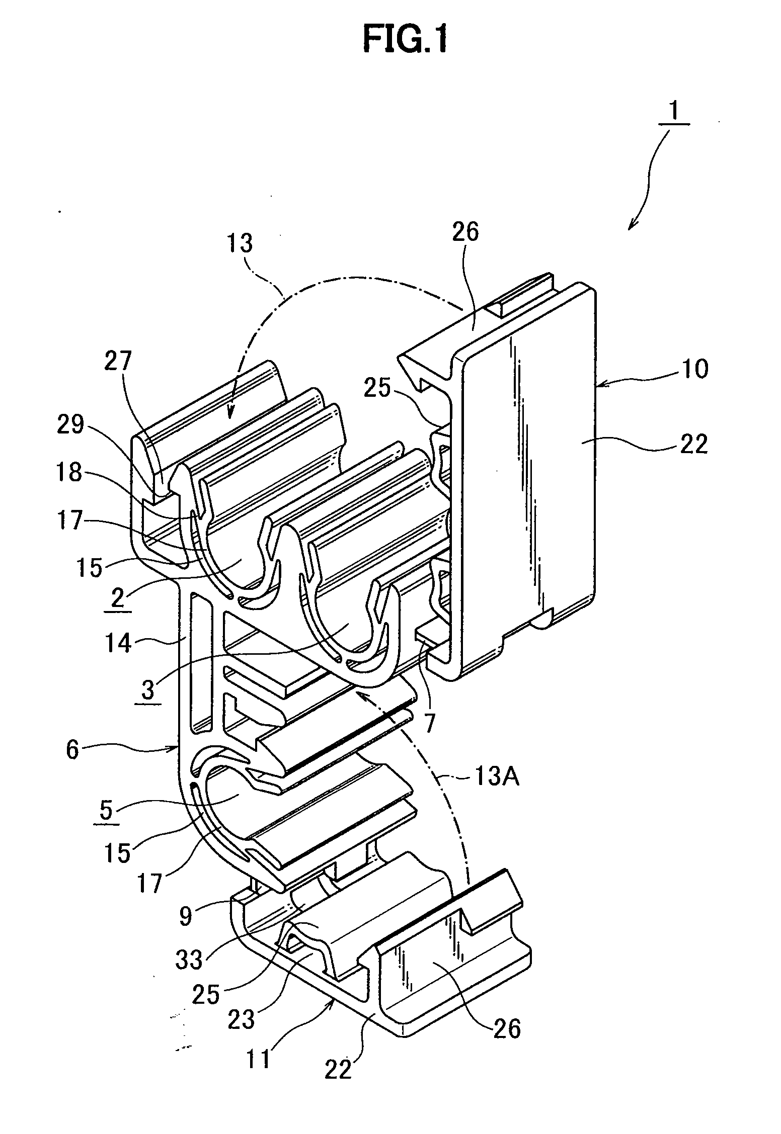
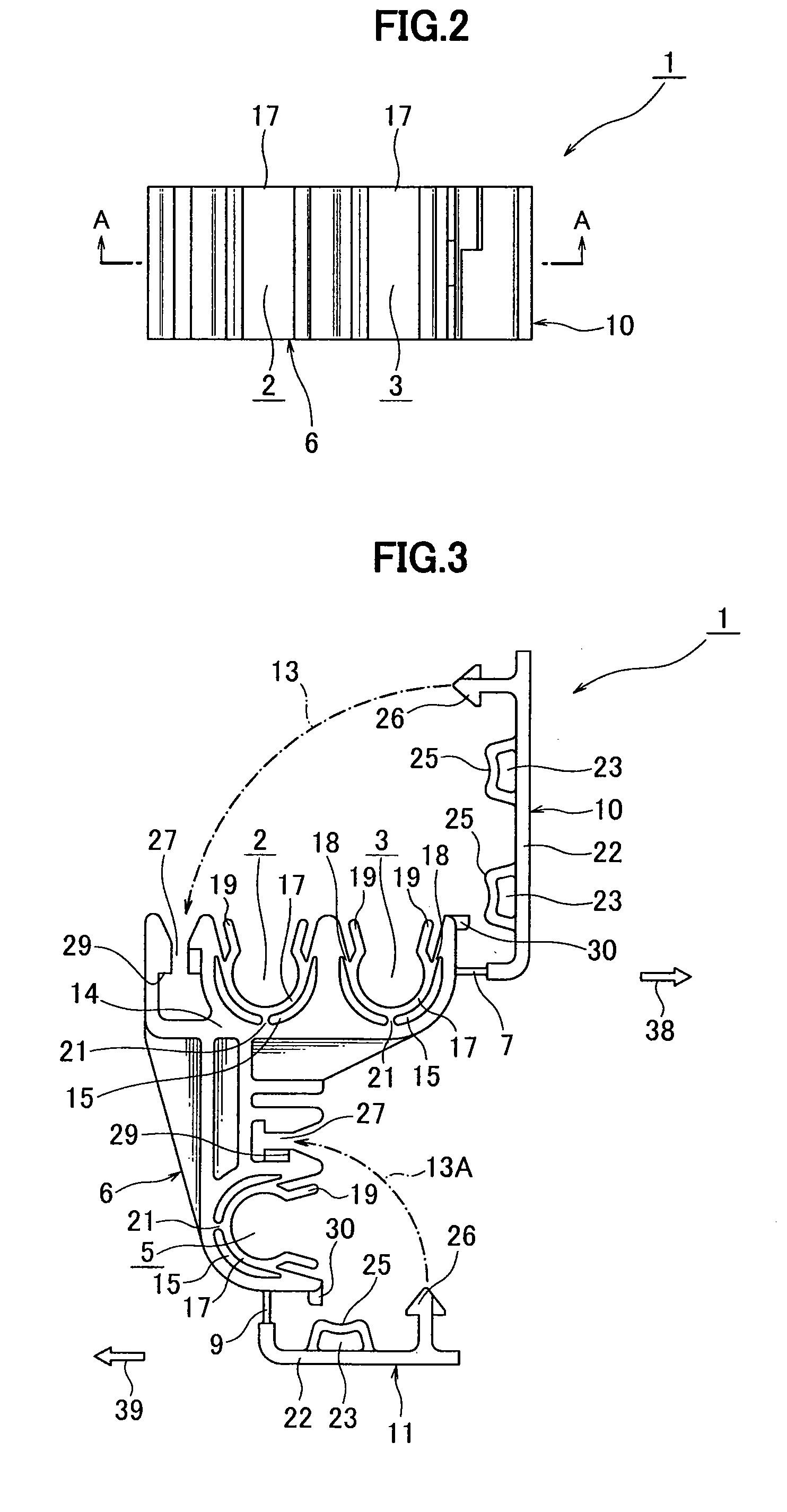
[0035] With reference to the drawings, a plurality of embodiments of the present invention will now be described. A vibration-insulation fastener 1 according to the present invention is designed to hold an elongated component such as a pipe, for example, a fuel pipe or a brake oil pipe, or a wire harness. This vibration-insulation fastener 1 for a pipe or the like will be described with reference to FIGS. 1 to 7. The vibration-insulation fastener 1 comprises: a base 6 having two U-shaped first clamps 2, 3 and a U-shaped second clamp 5 each formed to hold an elongated component, such as a pipe; a first cover 10 connected to the base 6 through a first hinge 7 to close respective openings of the first clamps 2, 3; and a second cover 11 connected to the base 6 through a second hinge 9 to close an opening of the second clamp 5. The base 6, the first and second hinges 7, 9 and the first and second covers 10, 11 of the vibration-insulation fastener 1 are integrally formed in one piece thro...
second embodiment
[0045] With reference to FIGS. 8 to 11, a vibration-insulation fastener 41 according to the present invention will be described, which permits the use of a single slide. The vibration-insulation fastener 41 has a number of common features with the vibration-insulation fastener 1. Thus, a description of features in common with the vibration-insulation fastener 1 will be omitted.
[0046] In the vibration-insulation fastener 41, a first cover 10A is connected to the base 6 through the first hinge 7 in such a manner as to have a swing direction opposite to that of the first cover 10 of the vibration-insulation fastener 1. The remaining structure is the same as that of the vibration-insulation fastener 1, and its description will be omitted. When the first cover 10A is closed to cover the first clamps 2, 3, it is pivotally moved in one direction (arrow 42) about the first hinge 7. As described in the first embodiment, the second cover 11 is pivotally moved about the second hinge 9 in a dir...
third embodiment
[0052] In the vibration-insulation fastener 47, each partial receiving member 50 in each of the clamps 2, 3 is formed with raised portions 54 different from the raised portion 46 of the vibration-insulation fastener 45 according to the Each raised portion 54 has a T-shape cross-section slightly protruding toward the corresponding base part 14 and having arms extending from a stem resiliently along a peripheral surface of the partial receiving member 50 to distal ends. This makes it possible to apply a reaction force to the partial receiving member 50 with enhanced resilience, so as to obtain further enhanced vibration absorbing function. Preferably, each base part 14 is formed with a second raised portion 55 (FIG. 18) at a position intermediate the T-shaped raised portion 54. The second raised portion 55 can restrict a radially outward bending of the partial receiving member 50. FIG. 19 shows a state after pipes 34, 35, 37 are held to each others by using the vibration-insulation f...
PUM
 Abstract
Description
Claims
Application Information