
Display support mechanism

a technology of display support mechanism and support rod, which is applied in the direction of stand/trestle, application, kitchen equipment, etc., can solve the problems of complicated rotational axis working, and achieve the effect of reducing the gross volume of the display support mechanism, increasing the number of simultaneously carriable display support mechanisms in shipment, and easy rotation

Inactive Publication Date: 2007-09-20
FUNAI ELECTRIC CO LTD
View PDF12 Cites 12 Cited by
  • Summary
  • Abstract
  • Description
  • Claims
  • Application Information

AI Technical Summary

Benefits of technology

[0012] In the display support mechanism according to the first aspect, the angles of the sectoral first hole and the sectoral second hole are preferably less than 90°, and the total angle of the sectoral first hole and the sectoral second hole is preferably at least 90°. According to this structure, the display screen can be inclined by at least 90°. Thus, the base and the display screen can be arranged in parallel with each other. Therefore, the gross volume of the display support mechanism can be so reduced that the number of simultaneously carriable display support mechanisms can be increased in shipment.
[0029] The display support mechanism according to the second aspect preferably further comprises a platelike stop member, the support shaft preferably includes a receiving hole receiving the stop member, and the stop member is preferably inserted into the receiving hole of the support shaft inserted into the first hole of the display screen support member and the second hole of the base support member, thereby preventing the support shaft from displacement. According to this structure, the easily workable platelike stop member can easily inhibit the support shaft from coming off the display screen support member and the base support member.

Problems solved by technology

In each of the display support mechanisms described in the aforementioned Japanese Patent Laying-Open Nos. 2005-140807, 2001-75486 and 2002-196686, however, the round shaft is employed as an axis of rotation and hence grooving or the like must be performed along the outer periphery of the round shaft for mounting a stop member such as a C-ring in order to prevent the round shaft from axial deviation, to disadvantageously result in complicated working of the axis of rotation.

Method used


Image

  • Display support mechanism
  • Display support mechanism
  • Display support mechanism

Examples


Embodiment Construction

[0043] An embodiment of the present invention is now described with reference to the drawings.

[0044] First, the structure of a display support mechanism 1 according to the embodiment of the present invention is described with reference to FIGS. 1 to 12.

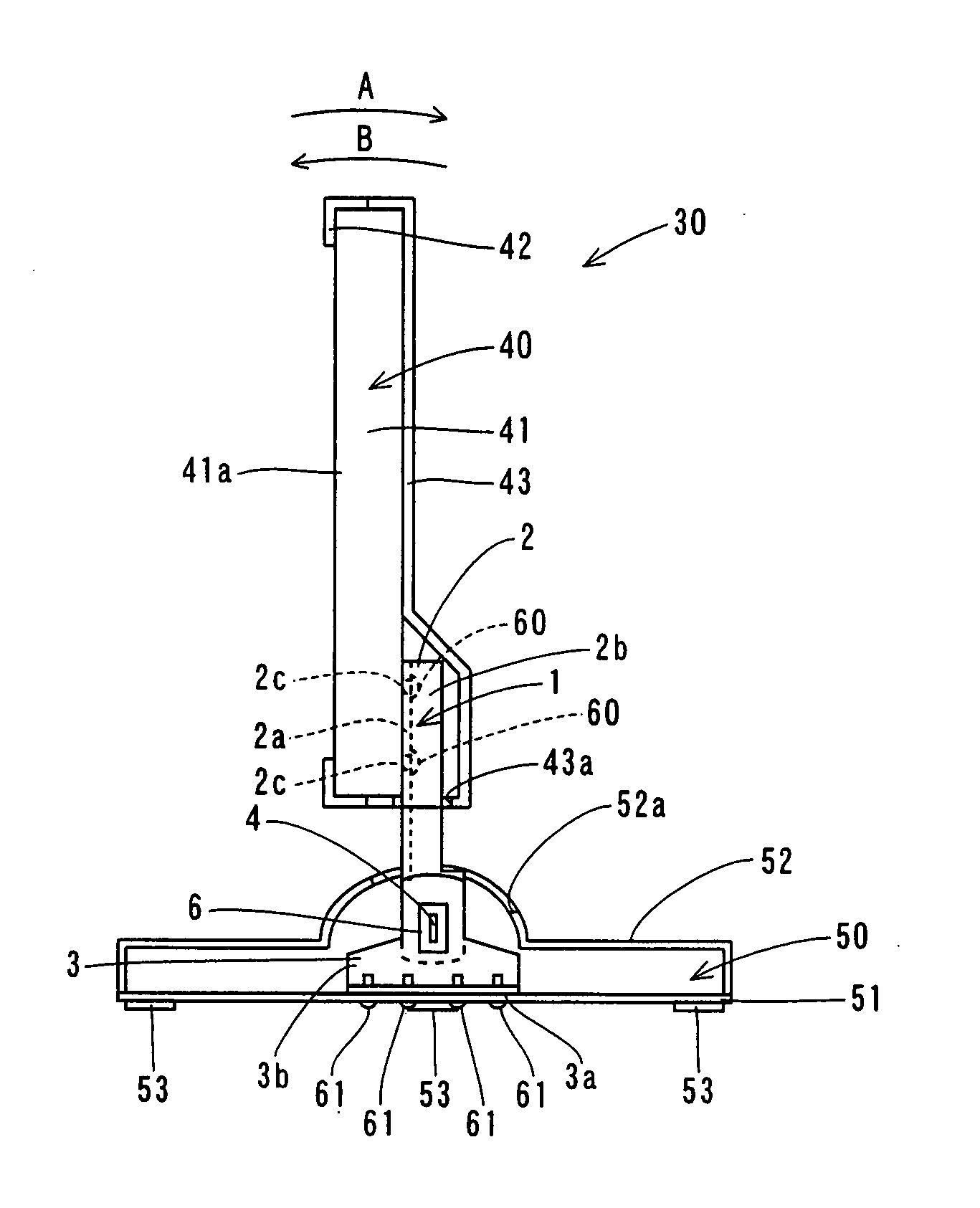
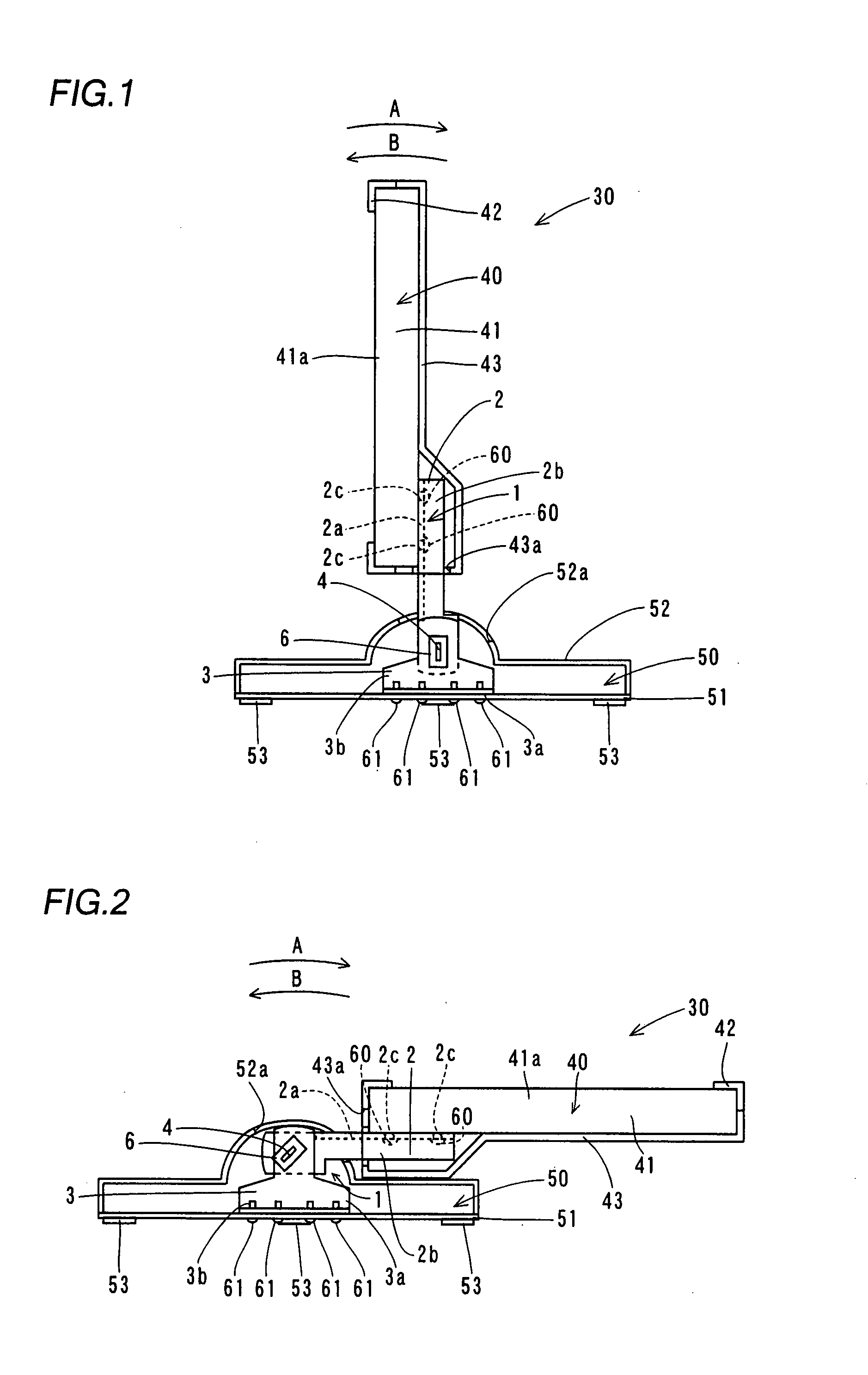
[0045] The display support mechanism 1 according to the embodiment of the present invention is provided for supporting a liquid crystal display portion 40 of a liquid crystal display 30, as shown in FIG. 1. This display support mechanism 1 is mounted on a base 50. The display support mechanism 1 supports the liquid crystal display portion 40 to be rotatable by 90° in a direction A (see FIG. 2) or by 10° in a direction B with respect to the base 50. The display support mechanism 1 is enabled to support the liquid crystal display portion 40 in a state inclined by a prescribed angle with respect to the base 50.

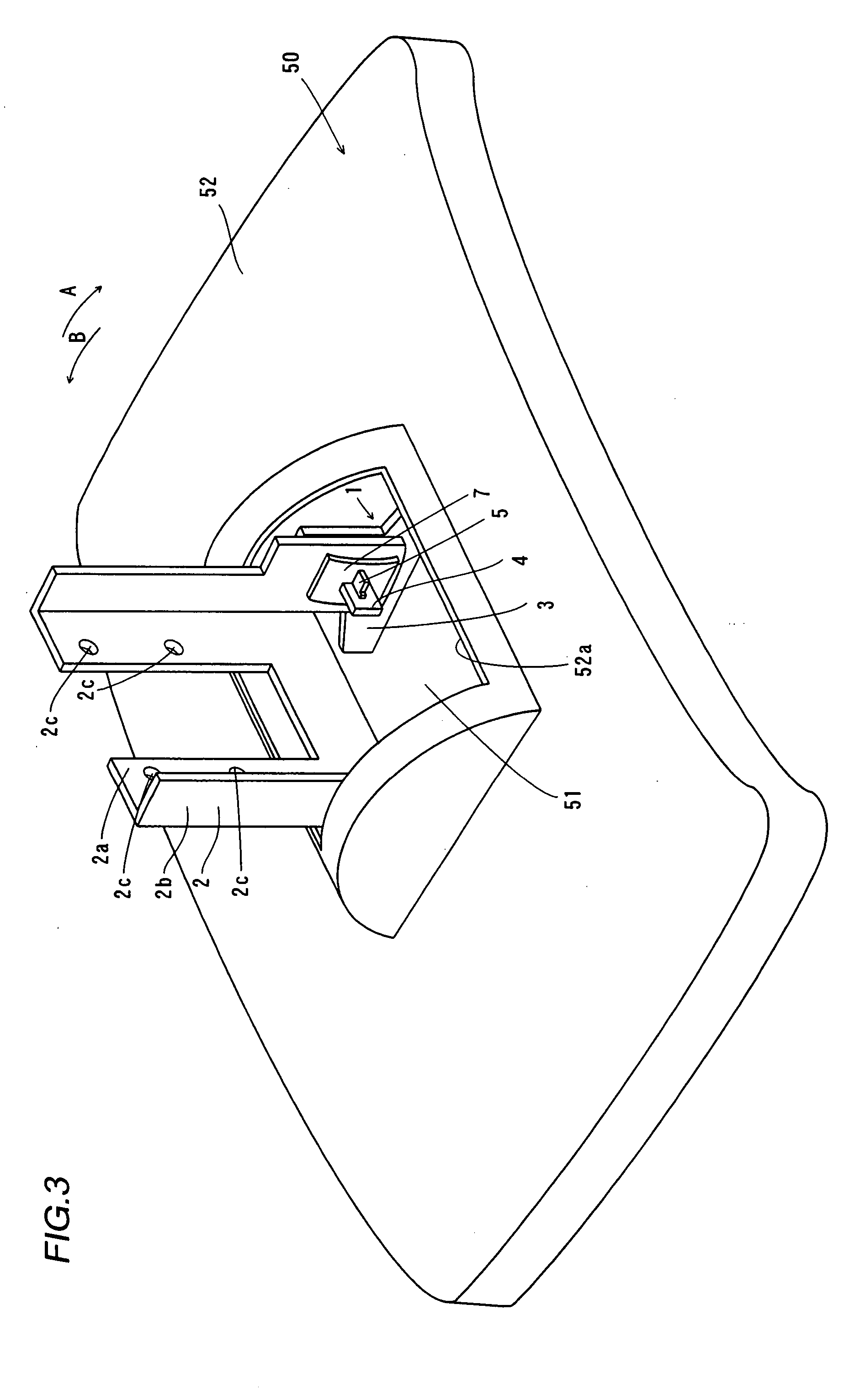
[0046] As shown in FIGS. 4 and 5, the display support mechanism 1 comprises a liquid crystal display portion support member 2,...


PUM


Abstract

A display support mechanism capable of inclining a display screen by a prescribed angle without employing a round shaft as an axis of rotation is obtained. This display support mechanism comprises a support shaft provided in the form of a plate, a display screen support member, supporting a display screen, having a sectoral first hole receiving the platelike support shaft and a base support member having a sectoral second hole receiving the platelike support shaft, while the display screen support member is rotatable about the support shaft serving as an axis of rotation in the total angular range of the sectoral first hole of the display screen support member and the sectoral second hole of the base support member.

Description

BACKGROUND OF THE INVENTION [0001] 1. Field of the Invention [0002] The present invention relates to a display support mechanism. [0003] 2. Description of the Background Art [0004] A display support mechanism capable of supporting a display screen in a state inclined by a prescribed angle is known in general, as disclosed in Japanese Patent Laying-Open No. 2005-140807, 2001-75486 or 2002-196686, for example. [0005] The display support mechanism described in the aforementioned Japanese Patent Laying-Open No. 2005-140807 comprises a stand post mounted on the side of a base, another stand post mounted on the side of a display screen and a slidable link coupling the stand posts mounted on the sides of the base and the display screen respectively to each other to be rotatable about a round shaft. In the display support mechanism described in Japanese Patent Laying-Open No. 2005-140807, the link is slid in a first direction for fixing the angle of the display screen, and slid in a second ...

Claims


Application Information

Patent Timeline
IPC IPC(8): F16M11/00
CPCF16M2200/08F16M11/10
Inventor SAWAI, KUNIOYOKOTA, KATSUYUKI
Owner FUNAI ELECTRIC CO LTD
Learn More