Vehicular Body Structure

a technology of vehicle body and body, applied in the direction of vehicular safety arrangements, roofs, pedestrian/occupant safety arrangements, etc., can solve the problems of inability to realize or realize the proposed pillarless vehicle, difficulty in securing sufficient strength of the vehicle body, and high construction complexity, so as to achieve simple structure, significant improvement of vision field, and no high manufacturing cost and labor hourly cost

Active Publication Date: 2007-09-20
HONDA MOTOR CO LTD
View PDF15 Cites 16 Cited by
  • Summary
  • Abstract
  • Description
  • Claims
  • Application Information

AI Technical Summary

Benefits of technology

[0014] With such arrangements of the corner windows, the present invention can achieve a significantly-improved field of vision, with a simple structure and without requiring high manufacturing cost and much labor hour, while securing sufficient vehicular body strength. Further, because the first and second right front pillars and the first and second left front pillars are provided in such a manner that, from the eye point position of the driver of the vehicle, they look as if extending vertically upright, the present invention can achieve an even-further-improved field of vision. Furthermore, because each of the first and second right front pillars and the first and second left front pillars has a horizontal width of 60 mm or below, the present invention can substantially eliminate any unwanted field-of-vision blocking area.

Problems solved by technology

The vehicles, in which pillars are dispensed with so as to avoid unwanted field-of-vision blocking areas, suffer from the problem of difficulty in securing sufficient strength of the vehicular body.
Thus, such proposed pillarless vehicles have not yet been actualized or realized due to the insufficient strength problem etc.
The vehicles with pillars of the truss construction having a multiplicity of triangular gaps, on the other hand, suffer from the problem that the construction is very complicated and manufacturing of the vehicle requires high cost and much labor hour.
Further, such a pillar construction would face limits to enhancement of visibility due to the trusses.

Method used


Image

  • Vehicular Body Structure
  • Vehicular Body Structure
  • Vehicular Body Structure

Examples


first embodiment

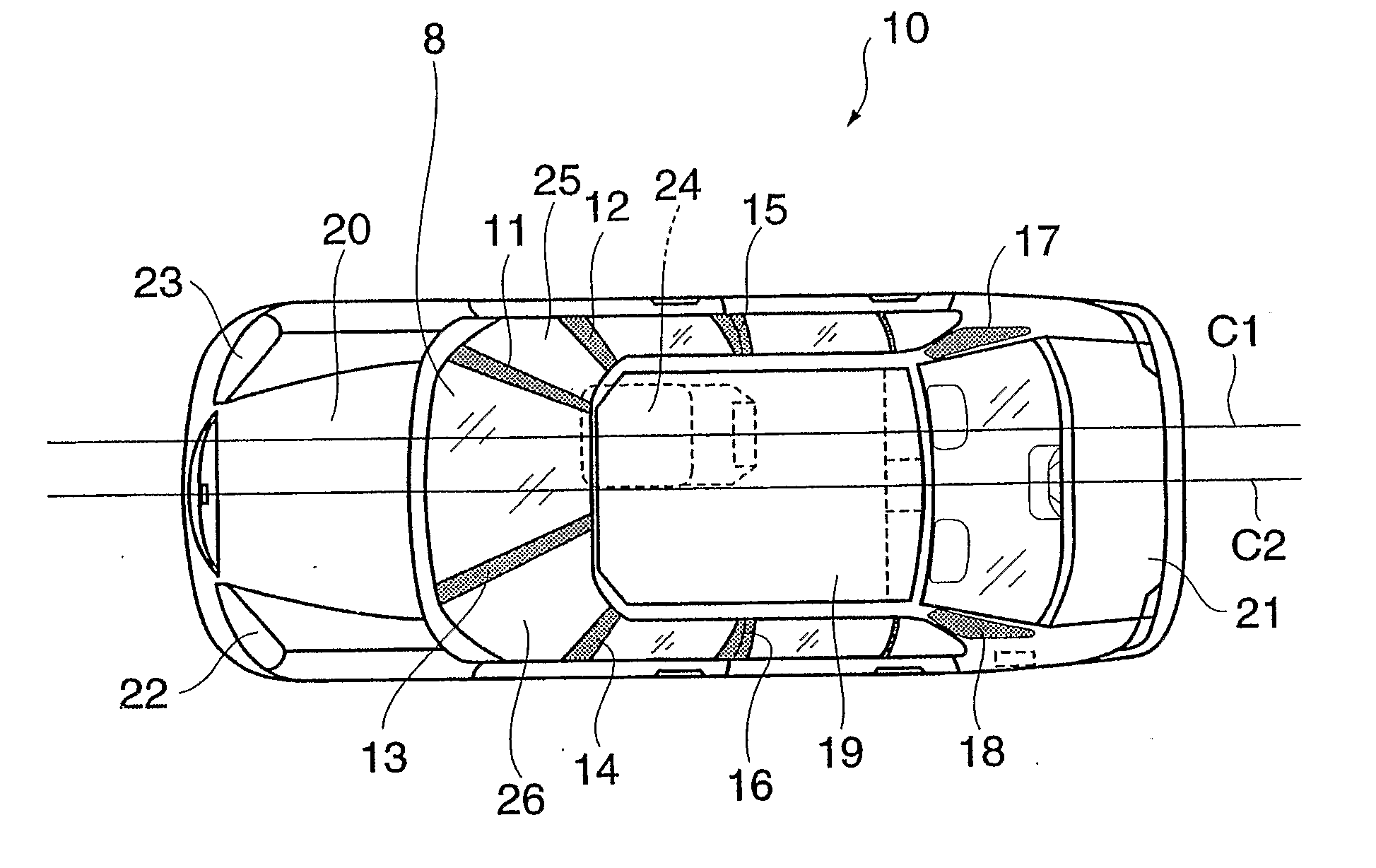
[0029]FIG. 1 is a plan view of a vehicle employing a body structure according to the present invention.

[0030] As seen in FIG. 1, the vehicle 10 includes first and second right front pillars 11 and 12, first and second left front pillars 13 and 14, side pillars 15 and 16, and right and left rear pillars 17 and 18. The vehicle 10 also includes a roof 19, bonnet 20, trunk lid 21, head lamps 22 and 23, and a driver seat 24 in the interior of a vehicle compartment. The positions of the side pillars 15 and 16 and the rear pillars 17 and 18 are generally the same as those in the conventional counterparts.

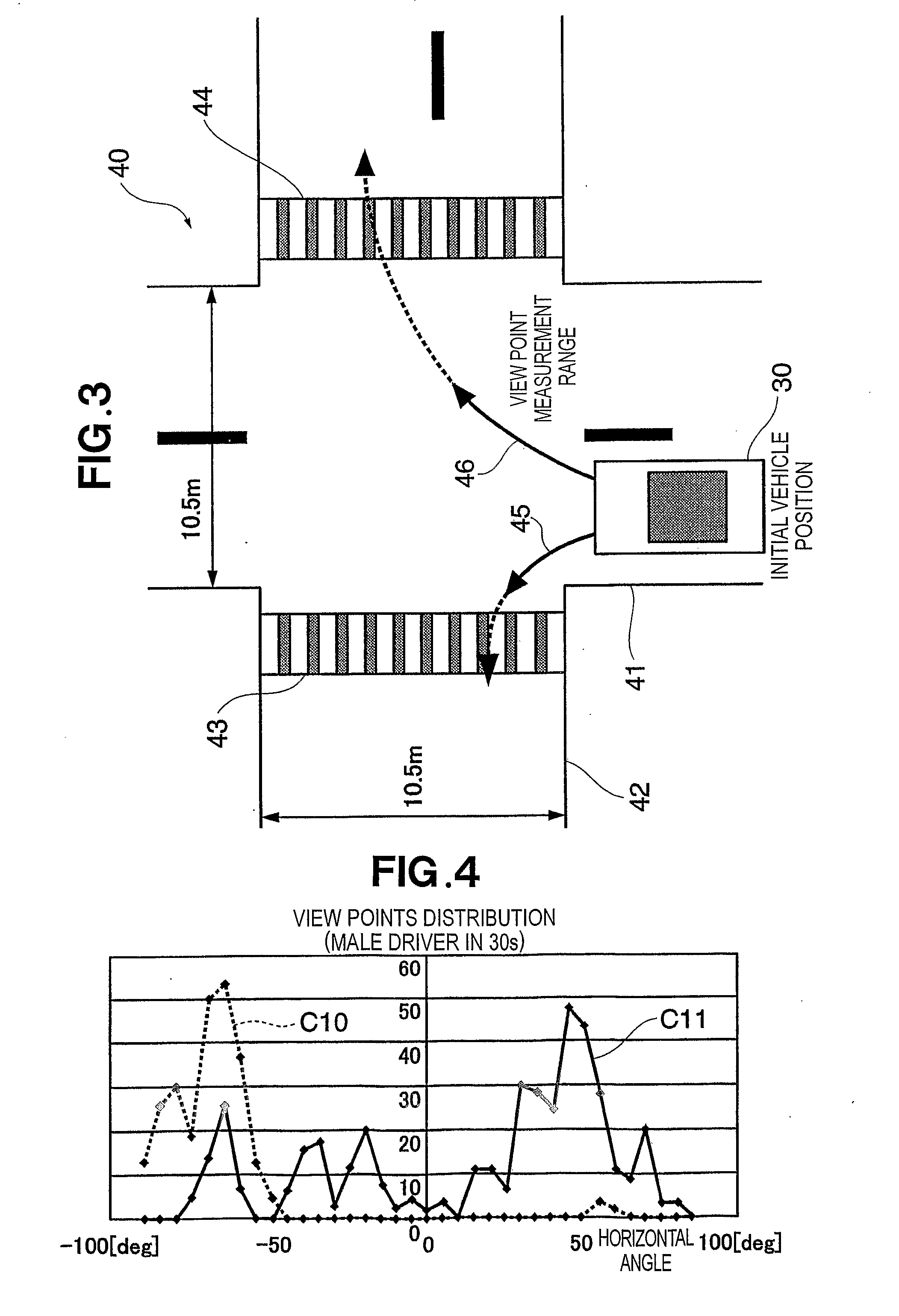
[0031] The front pillars 11, 12, 13 and 14 are provided at positions that can avoid, or do not agree with, peak positions in distribution of view points—measured as a test driver turned a test vehicle, equipped with no pillar, to the left and right in later-described experimental tests—, and a neighborhood of the peak positions. The view points and viewing angle differ more or less among ...

second embodiment

[0055]FIG. 9 is a plan view of a vehicular body structure according to the present invention.

[0056] The second embodiment is generally similar to the first embodiment except that the left and right A′ pillars (auxiliary or second pillars) in the first embodiment are not included in the second embodiment. In FIG. 9, the same elements as those in the first embodiments are indicated by the same reference numerals as in FIG. 1 and will not be described here to avoid unnecessary duplication. The second embodiment is characterized in that it can secure sufficient vehicular body strength despite a greater door window opening; in this embodiment too, the pillars are disposed at positions of low view point frequency identified from the aforementioned experimental tests. With such arrangements, the second embodiment can even further improve the field of vision.

[0057] Although the present embodiment has been described in relation to a right-hand-steering-wheel vehicle, the present invention m...


PUM


Abstract

In a vehicular body structure, left and right front pillars are provided closer to the longitudinal centerline of a vehicle than left and right corner sections of a compartment of the vehicle. First corner window (26) provided adjacent to one of the left and right front pillars (13) which is more remote from a driver's seat (24) has a greater opening area than a second corner window (25) provided adjacent to the other of the left and right pillars (11) which is closer to the driver's seat.

Description

TECHNICAL FIELD [0001] The present invention relates to vehicular body structures, and more particularly to a novel vehicular body structure having front pillars designed to improve a field of vision (or range of vision) of a vehicle driver. BACKGROUND ART [0002] To date, various improvements have been made to four-wheeled motor vehicles to achieve enhanced comfort, performance and various efficiencies of the vehicles. For example, improvements have been made to the sectional shape and material of front pillars such that the front pillars can provide a sufficient vehicular body strength while securing certain good viewing fields in diagonally forward left and right directions. Especially, in making left and right turns at intersections, each vehicle driver is required to carefully look, i.e., visually confirm conditions, around the vehicle, e.g. to the left and right of the vehicle as well as in front of the vehicle. In thus visually confirming safe conditions around the vehicle, th...

Claims


Application Information

Patent Timeline
Patent Type & Authority Applications(United States)
IPC IPC(8): B60J1/02
CPCB62D25/04
Inventor MATSUMOTO, YOSHIYUKITSUTSUMI, YOJIROABE, MASAAKIUEMATSU, ISAOMARUYAMA, KAZUYUKI
Owner HONDA MOTOR CO LTD
Why Eureka
Try Eureka