Antenna device with radiation pattern adjustment element
- Summary
- Abstract
- Description
- Claims
- Application Information
AI Technical Summary
Benefits of technology
Problems solved by technology
Method used
Image

Examples
first embodiment
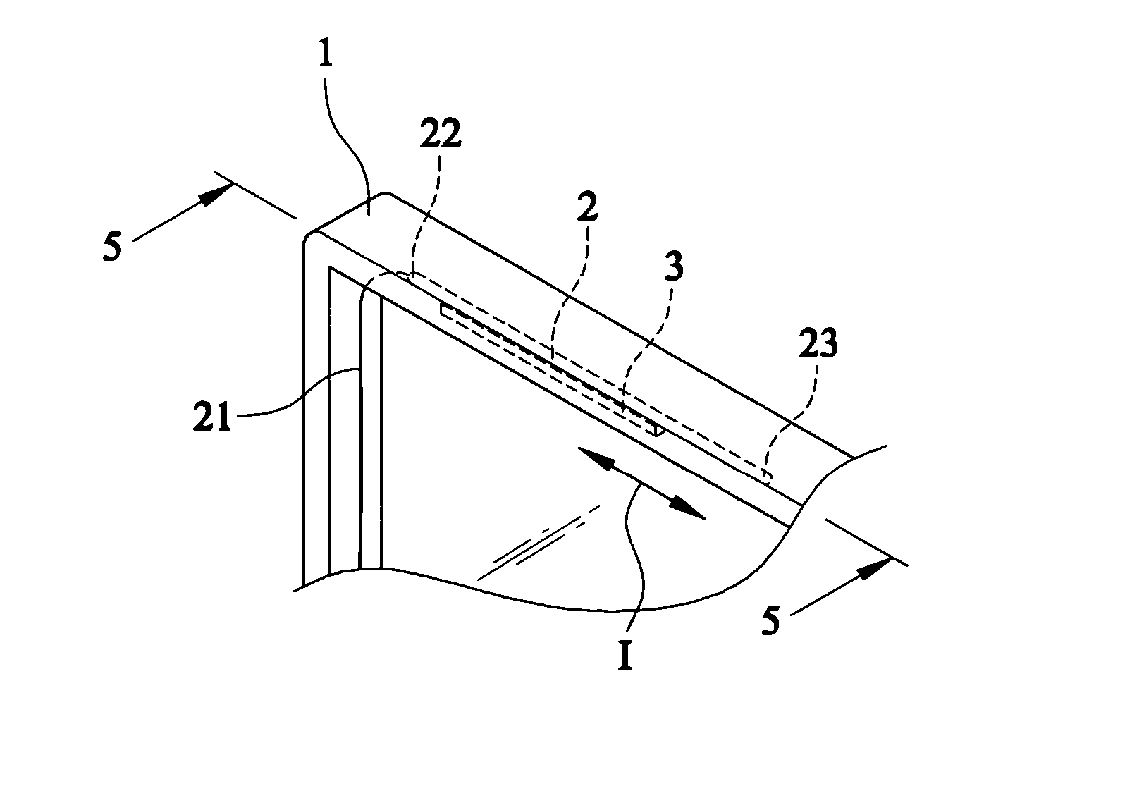
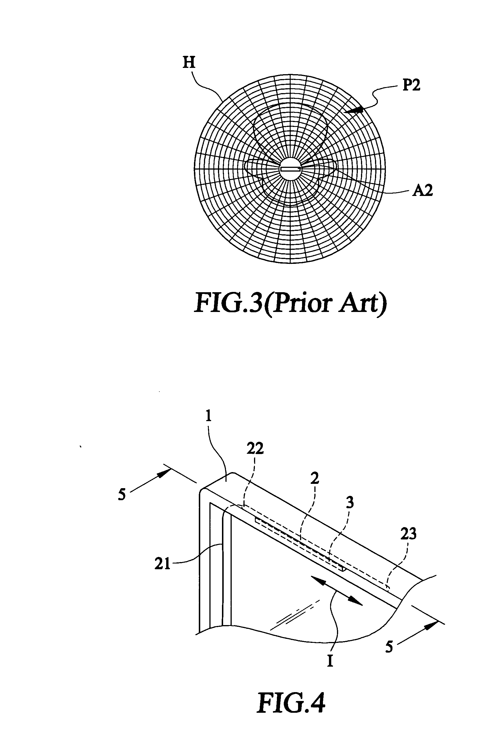
[0033] With reference to the drawings and in particular to FIGS. 4 and 5 that are an assembled perspective view of an antenna device with an established radiation pattern adjustment element in accordance with the present invention and a sectional view taken along line 5-5 of FIG. 4. As shown in the figures an electronic device, which is generally denoted a numeral reference 1, includes an antenna element 2, which is an omni-directional antenna, and a radiation pattern adjustment element 3.
[0034] The antenna element 2 is electrically connected to an antenna signal feeding line 21 to electrically conduct the wireless signals between the antenna element 2 and the electronic device 1. The antenna element 2 further includes a signal-feeding end 22 and a terminal end 23, wherein the signal-feeding end 22 electrically connects the antenna signal feeding line 21. Besides, the radiation pattern adjustment element 3 is arranged at a position below the antenna element 2, and the radiation patt...
second embodiment
[0037] With reference to FIGS. 8 and 9 that are an assembled perspective view of an antenna device with radiation pattern adjustment element in accordance with the present invention and a sectional view taken along line 9-9 of FIG. 8. As shown in the figures, an electronic device 1 includes an antenna element 2 and multiple radiation pattern adjustment elements 31 and 32, wherein the antenna element 2 is an omni-directional antenna.
[0038] The antenna element 2 is electrically connected to an antenna signal feeding line 21 to conduct the wireless signals between the electronic device 1 and the antenna element 2. Further, the antenna element 2 also includes a signal-feeding end 22 and a terminal end 23, wherein the signal-feeding end 22 electrically connects the antenna signal feeding line 21. Moreover, the radiation pattern adjustment elements 31 and 32 are arranged at positions beside the antenna element 2 and in a direction parallel to an extended direction I of the antenna element...
third embodiment
[0040]FIG. 11 is an exploded perspective view of an antenna device with a radiation pattern adjustment element in accordance with the present invention. As shown in the figure, an electronic device 1 includes an antenna device 2′, which is a directional antenna, and a radiation pattern adjustment element 3′. The antenna element 2′ is electrically connected to an antenna signal feeding line 21′ to conduct the wireless signals between the electronic device 1 and the antenna element 2′. The antenna element 2′ further includes a signal-feeding end 22′ and a terminal end 23′, wherein the signal-feeding end 22′ serves as a mean to connect the antenna signal feeding line 21′. In addition, the radiation pattern adjustment element 3′ is arranged below the antenna element 2′ and in a direction parallel to an extended direction I of the antenna element 2′.
[0041] As shown in FIG. 12, which is an established radiation pattern in accordance with the third embodiment of the present invention, the ...
PUM
 Abstract
Description
Claims
Application Information
 - R&D
- Intellectual Property
- Life Sciences
- Materials
- Tech Scout
- Unparalleled Data Quality
- Higher Quality Content
- 60% Fewer Hallucinations
Browse by: Latest US Patents, China's latest patents, Technical Efficacy Thesaurus, Application Domain, Technology Topic, Popular Technical Reports.
© 2025 PatSnap. All rights reserved.Legal|Privacy policy|Modern Slavery Act Transparency Statement|Sitemap|About US| Contact US: help@patsnap.com