Light source calibration and adjustment for scanning printer

a scanning printer and light source technology, applied in the field of scanning printers, can solve the problems of leds having a tendency to degrade with us

Inactive Publication Date: 2007-09-20
IBM CORP
View PDF8 Cites 13 Cited by
  • Summary
  • Abstract
  • Description
  • Claims
  • Application Information

AI Technical Summary

Problems solved by technology

One problem with use of LED elements is that LEDs have a tendency to degrade with use.

Method used


Image

  • Light source calibration and adjustment for scanning printer
  • Light source calibration and adjustment for scanning printer
  • Light source calibration and adjustment for scanning printer

Examples


Embodiment Construction

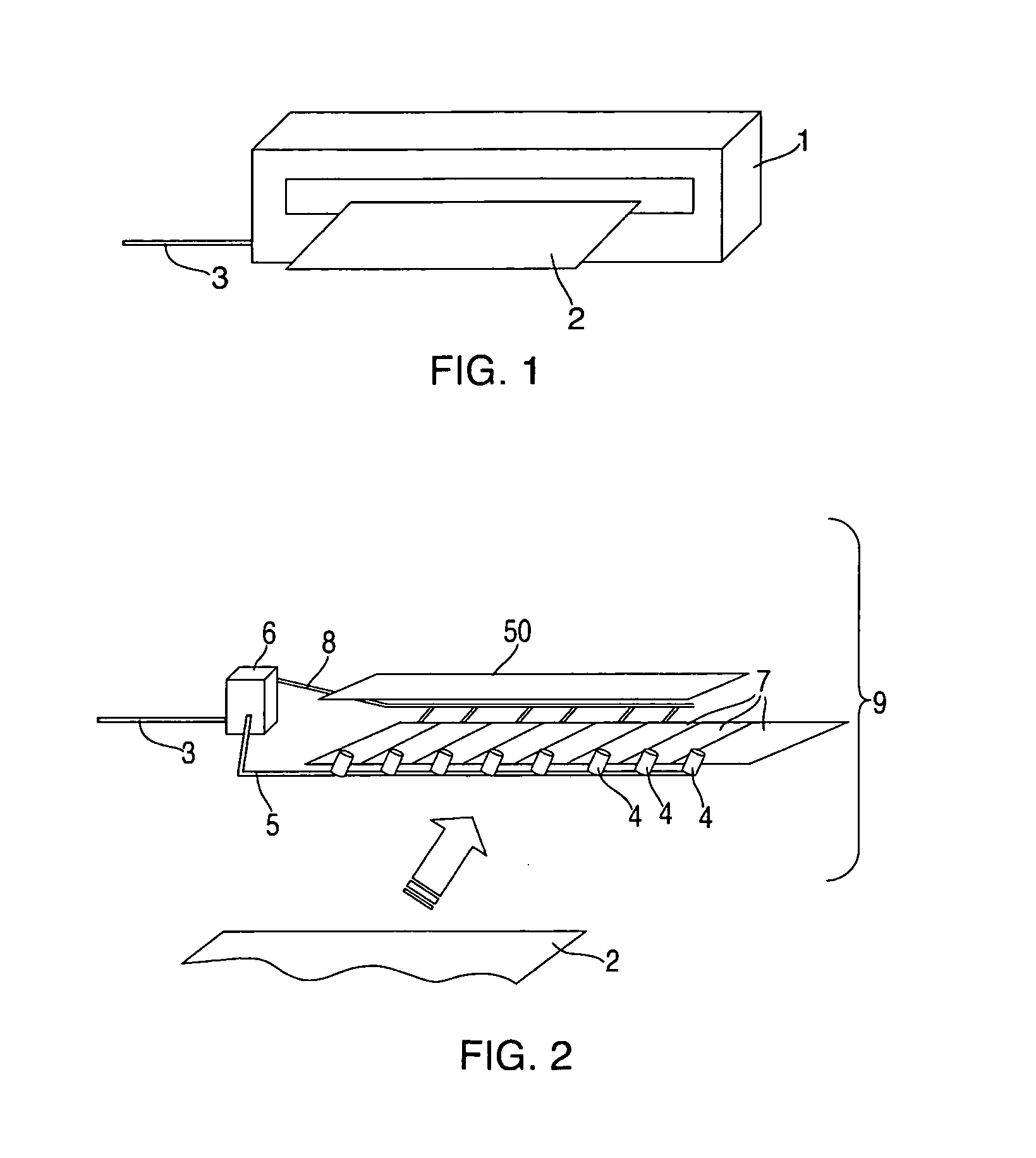
[0020] Referring to FIG. 1, there are shown to aspects of printer 1. In the illustration provided, the printer 1 includes scanning functions. A document for scanning, referred to as a “scan sheet 2” is fed into the printer 1. The printer 1 is powered by a power supply 3 that provides current and voltage. As used herein, the scan sheet 2 is generally synonymous with and may be referred to as a “document,” as a “target” and as a “calibration standard.”

[0021] Referring to FIG. 2, there are shown aspects of a scanning unit 9 for the printer 1. In the embodiment illustrated, the scanning unit 9 (also referred to as a scanner 9) includes an array of LEDs 4 and an array of pixels 7. Typically, the array of pixels 7 is provided as elements of a charged coupled device (CCD). Although discussed herein as using a CCD, this embodiment is non-limiting. For example, it should be recognized that other similar devices such as a complementary metal-oxide-semiconductor device (CMOS) may be used.

[002...


PUM


Abstract

A scanning printer including a scanner unit having an adjustable scanning light output may be adjusted by determining a minimum response for each pixel and a maximum response for each pixel when scanning a calibration document and setting the light output to correlate to a maximum response value. The scanner unit may include a reference plate for internal and routine performance adjustments which include comparison of initial and operational response to the reference plate. Performance adjustments may be designed to account for and overcome various typical operational problems encountered with frequent use.

Description

TRADEMARKS [0001] IBM 8 is a registered trademark of International Business Machines Corporation, Armonk, N.Y., U.S.A. Other names used herein may be registered trademarks, trademarks or product names of International Business Machines Corporation or other companies. BACKGROUND OF THE INVENTION [0002] 1. Field of the Invention [0003] This invention relates to scanning printers and particularly to calibration of LED and CCD therein. [0004] 2. Description of Background [0005] A CCD contact scanner can be used for various image capture functions. Often, the scanner includes multiple light-emitting diode (LED) elements for illumination as well as a device for sensing light. Typically, the sensing device is a charge coupled device (CCD). Each CCD includes a number of pixels for sensing the illumination. Typically, the LED elements and the CCD circuit elements have a wide tolerance in light output and sensitivity, respectively. One problem with use of LED elements is that LEDs have a tend...

Claims


Application Information

Patent Timeline
Patent Type & Authority Applications(United States)
IPC IPC(8): B41J2/385
CPCH04N1/00002H04N1/00013H04N1/00015H04N1/00031H04N1/00045H04N1/00053H04N1/40056H04N1/00087H04N1/02815H04N1/02865H04N1/02885H04N1/032H04N1/00063
Inventor BLAIR, BRIAN E.BUI, TUYENCATO, ROBERT T.MYERS, ROBERT A.PRAKASH, RAVINDER
Owner IBM CORP
Why Eureka
Try Eureka