System performance correction by modifying refrigerant composition in a refrigerant system

a refrigerant system and composition technology, applied in refrigeration components, liquefaction, light and heating equipment, etc., can solve the problems of reducing the leakage of refrigerant components in the mixture more than the others, so as to reduce the amount of cycling, reduce the current, and reduce the unit capacity

Inactive Publication Date: 2009-07-02
CARRIER CORP
View PDF15 Cites 6 Cited by
  • Summary
  • Abstract
  • Description
  • Claims
  • Application Information

AI Technical Summary

Benefits of technology

[0008]As one example, should excess unit delivered capacity be identified, a partial or complete changeover could occur from a typically higher pressure refrigerant to a lower pressure refrigerant (a high pressure refrigerant is broadly defined as a refrigerant that has a higher pressure than a low pressure refrigerant for the same saturation temperature). This typically would then result in lower unit capacity, and would reduce the amount of cycling.
[0009]In such circumstances, the agency qualification (such as UL, CSA, etc.) for the system would typically be automatically granted, and need not be redone. This should be true since the refrigerant system, and its compressor, will be operating at a lower pressure and lower current, should a higher pressure refrigerant be replaced with a lower pressure refrigerant. Thus, unit cycling losses can be substantially reduced, system reliability enhanced and comfort in the conditioned space significantly improved. By reducing cycling, the present invention will address all these concerns. The refrigerant addition can also be made on an iterative basis, where the unit performance is checked after a new refrigerant has been added to the system and a portion of the old refrigerant is removed (if necessary). If the system performance still remains unsatisfactory, then an additional amount of the new refrigerant is added to the system. As the new refrigerant is added, it may also be desirable to remove, add or maintain the same level of the old refrigerant in the system.

Problems solved by technology

This typically would then result in lower unit capacity, and would reduce the amount of cycling.
If the system performance still remains unsatisfactory, then an additional amount of the new refrigerant is added to the system.
As a system refrigerant leak develops, some of the refrigerant components in the mixture can leak more than the others.

Method used


Image

  • System performance correction by modifying refrigerant composition in a refrigerant system
  • System performance correction by modifying refrigerant composition in a refrigerant system

Examples


Embodiment Construction

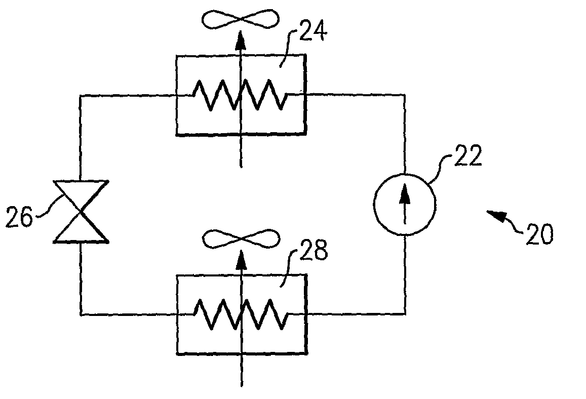
[0015]As shown in FIG. 1, a refrigerant system 20 includes a compressor 22 compressing a refrigerant and delivering it downstream to a condenser 24. Refrigerant passes from the condenser 24 to an expansion device 26, and then to an evaporator 28. As is known, the condenser in a conventional air conditioning system is typically located outdoors, and delivers heat to the ambient environment. The evaporator is typically positioned indoors, and conditions air to be delivered into a building. As also known, refrigerant circulates between the four basic components, 22, 24, 26 and 28 interconnected in a closed-loop arrangement. Many other subsystems and components are often included in refrigerant systems. However, for purposes of explaining this invention, all that is necessary is to understand the basic refrigerant system schematic and operation.

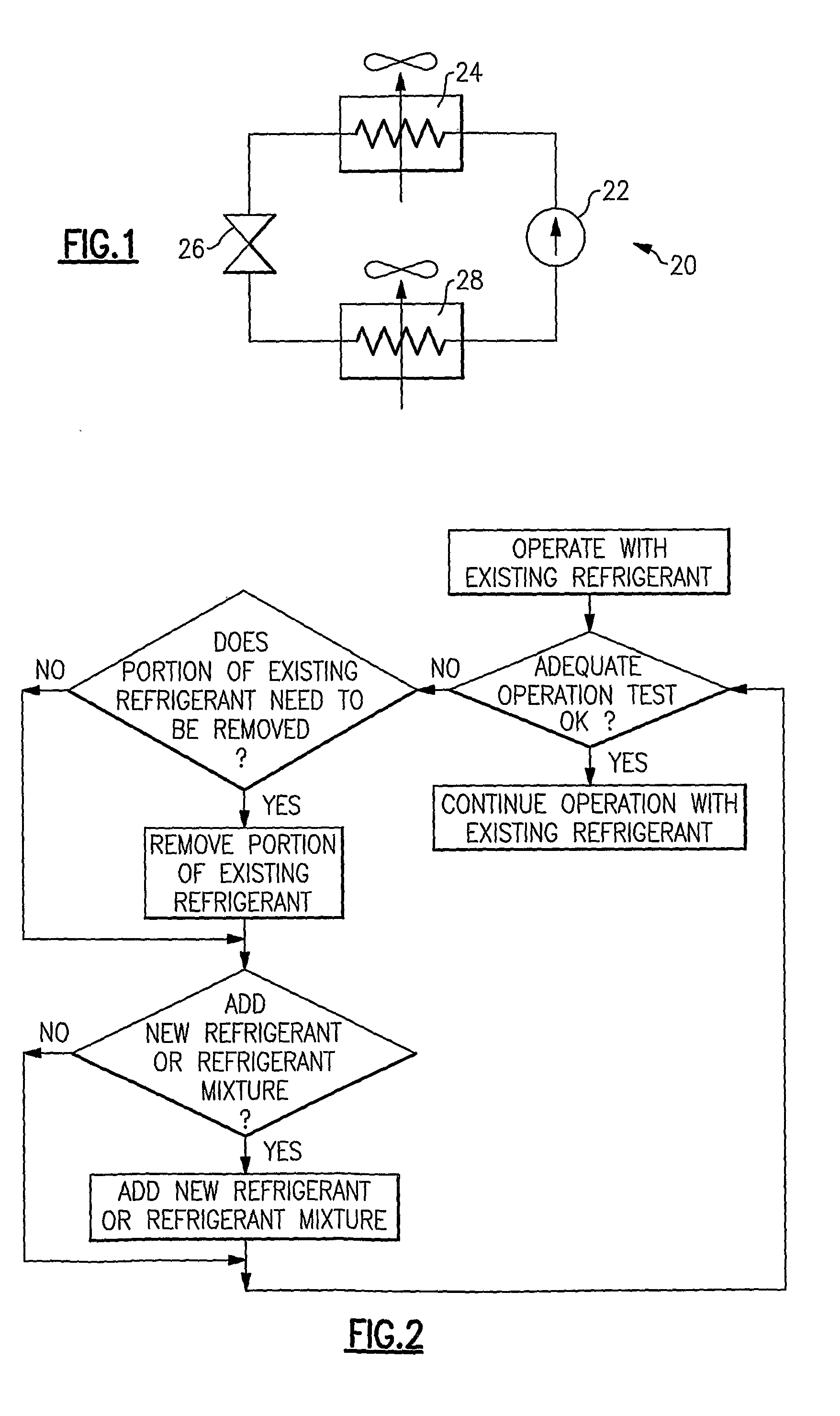
[0016]When it has been determined that the refrigerant system 20 is operating less than optimally, a decision can be made to partially or fully ...


PUM


Abstract

An adequate operation and performance of a refrigerant system includes the steps of adding a refrigerant that is different from the original refrigerant, into the refrigerant system should any operational problems be observed during operation of the refrigerant system. As an example, should the refrigerant system be cycling frequently, a lower pressure refrigerant may be added or replace, partially or fully, the refrigerant the system being initially charged with. By making this change, the present invention can, for example, lower the provided system capacity, and hence reduce the amount of cycling. Additionally, conditioned space comfort and system reliability would be improved. Further, changes over time, such as the degradation of the heat exchanger performance, and their negative effect on system operation can be alleviated by such a refrigerant substitution.

Description

BACKGROUND OF THE INVENTION[0001]This invention relates to correcting system performance of a refrigerant system by modifying the refrigerant composition in the refrigerant system.[0002]Refrigerant systems are employed to change the temperature and / or humidity of a secondary fluid. One common example is an air conditioning or heat pump system, which is utilized to condition air to be delivered into an indoor environment. Another example is a chiller system delivering chilled water or glycol solution for cooling purposes.[0003]As known, a typical vapor compression refrigerant system includes a compressor for compressing a refrigerant, a condenser downstream of the compressor, an expansion device downstream of the condenser, and an evaporator downstream of the expansion device. Refrigerant circulates between these four basic components, and a number of other optional components and sub-circuits.[0004]One control feature that is often incorporated into a refrigerant system is the abili...

Claims


Application Information

Patent Timeline
Patent Type & Authority Applications(United States)
IPC IPC(8): F25B45/00F25B1/00
CPCC09K5/045F25B9/006F25J1/0249F25B2500/18F25J1/02F25B45/00
Inventor LIFSON, ALEXANDERTARAS, MICHAEL F.
Owner CARRIER CORP
Why Eureka
Try Eureka