
Distance measuring device and laser beam projector therefor

a technology of distance measuring and laser beam, which is applied in the direction of measuring devices, projectors, instruments, etc., can solve the problems of affecting the accuracy of detecting a front-going vehicle, affecting the accuracy of detecting a vehicle that is somewhat to the side in front of the vehicle, and the structure of the mirror driving mechanism is too complicated or requires a higher data processing speed, so as to increase the curvature of the reflecting surface, improve the accuracy, and increase the curvatur

Inactive Publication Date: 2007-09-20
ORMON CORP
View PDF4 Cites 9 Cited by
  • Summary
  • Abstract
  • Description
  • Claims
  • Application Information

AI Technical Summary

Benefits of technology

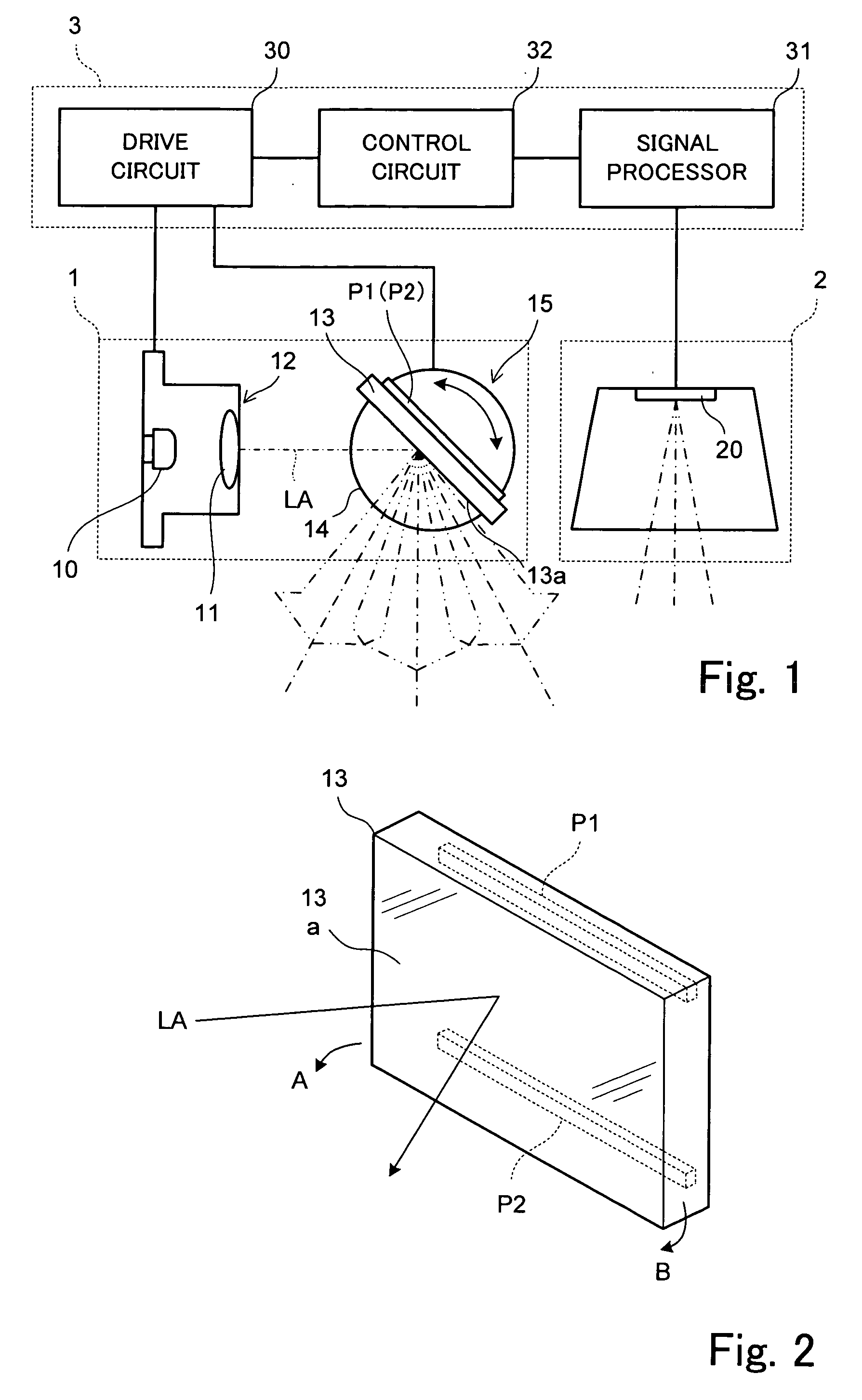
[0008]A laser beam projector according to this invention comprises a laser light source that outputs a laser beam, a light projecting mirror for reflecting the laser beam outputted from the laser light source and a mirror driving device for oscillating the light projecting mirror and thereby scanning a specified area with the laser beam. The mirror driving device serves to scan the area at least horizontally in the left-right direction or vertically in the up-down direction by rotationally driving the light projecting mirror of a flat planar shape. The laser beam projector of this invention is characterized as having at least one piezoelectric element attached to a back surface of the light projecting mirror. If a voltage is applied to the piezoelectric element, a force is experienced by the mirror due to the piezoelectric effect. Thus, the light projecting mirror can be deformed to make its reflecting surface concave or convex by attaching piezoelectric elements at appropriate positions on its back surface so as to control the spread of the laser beam. If a voltage is applied to the piezoelectric elements in synchronism with the rotary motion of the light projecting mirror, the continuity in the spread angle of the laser beam can be maintained.
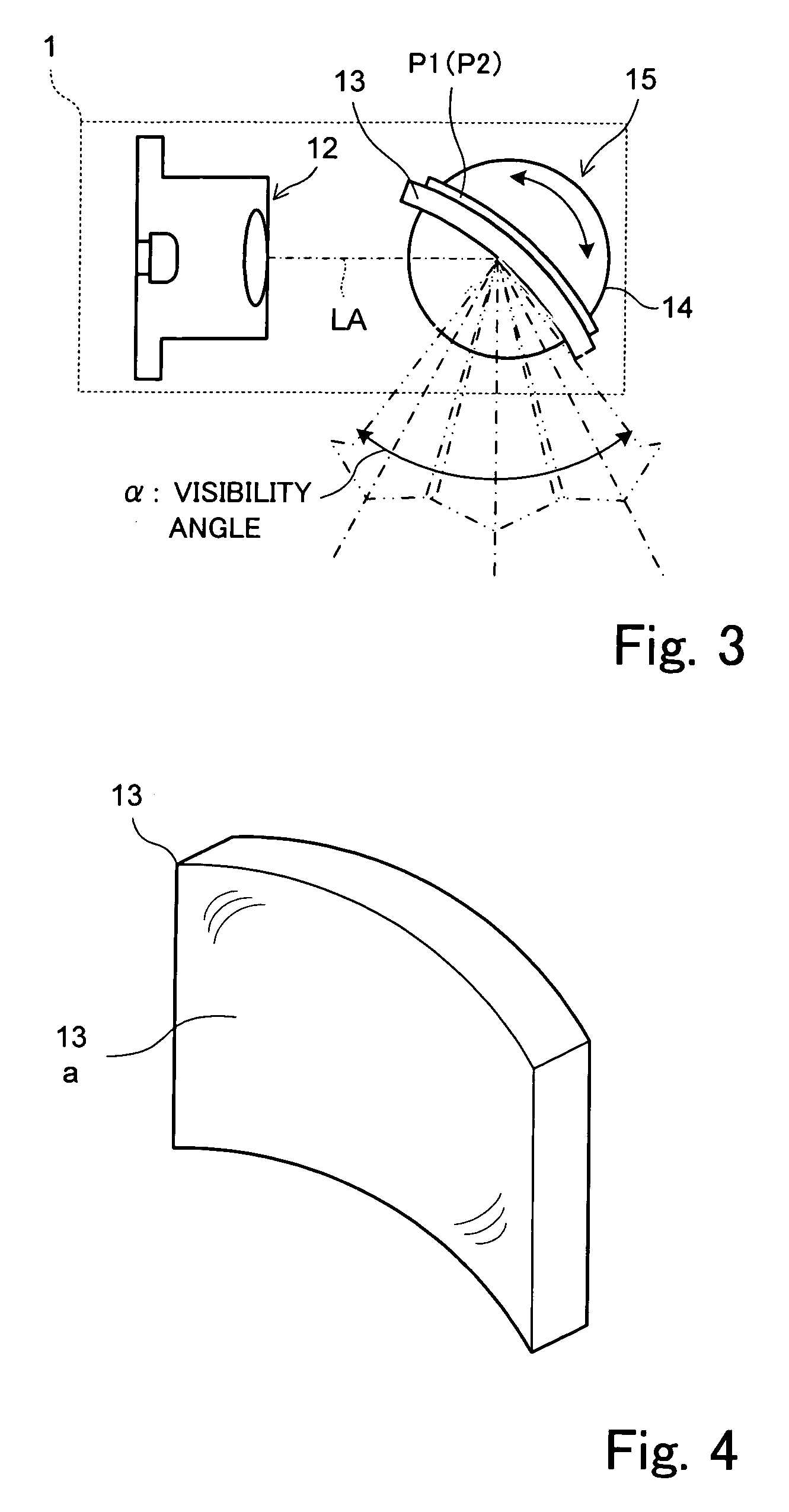
[0010]When a laser beam projector of this invention is applied to a distance measuring device mounted to a vehicle, the light projecting mirror is deformed by activating the piezoelectric elements to increase the curvature of its reflecting surface when the angle of oscillation of the light projecting mirror is nearly at its maximum. In this way, a front going vehicle can be traced and monitored with a high level of accuracy by means of a narrow laser beam when it is scanning the center area in front while a spreading beam can be used to detect pedestrians and obstacles somewhat to the left and to the right in front. The curvature of the reflecting surface may be increased as the angle of oscillation approaches the maximum value. A spreading beam is less accurate than a narrow beam but there is no problem if the purpose is to merely detect the presence of a pedestrian.

Problems solved by technology

As a result, when the own vehicle is traveling inside a city, for example, pedestrians who are somewhat to the side in front of the vehicle may fail to be detected because the range of the scan is too narrowly limited.
The former method affects the accuracy of detecting a front going vehicle adversely.
As for the latter method, it tends to cause the structure of the mirror driving mechanism to become too complicated or to require a higher speed of data processing, and the method becomes too expensive to carry out.
With the device described above, however, it takes a finite length of time to switch between the regularly and diffusively reflecting mirrors.
It is also inconvenient to choose the diffusively reflecting mirror in the city because the accuracy of detecting a front vehicle is not high.

Method used


Image

  • Distance measuring device and laser beam projector therefor
  • Distance measuring device and laser beam projector therefor
  • Distance measuring device and laser beam projector therefor

Examples


Embodiment Construction

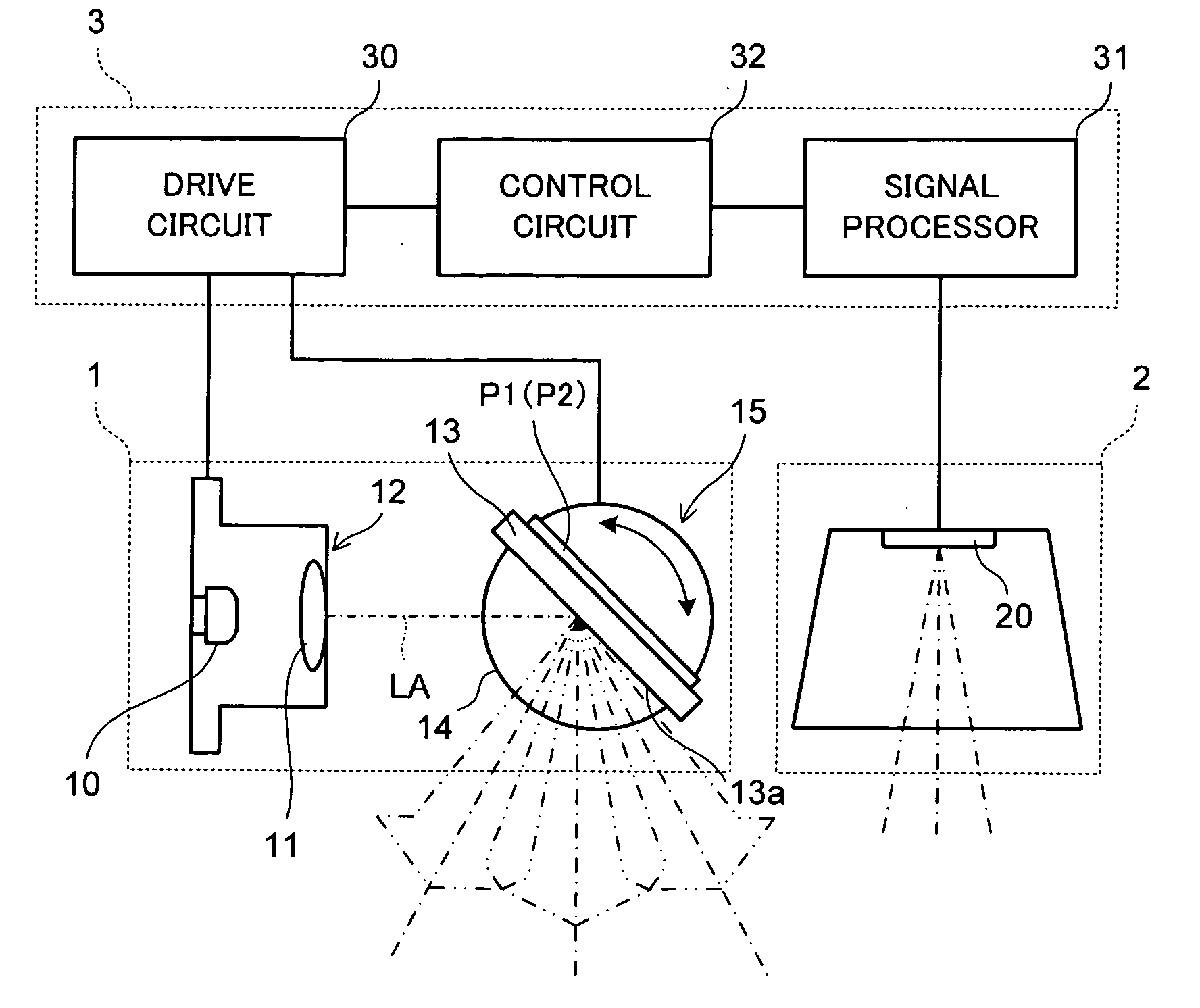
[0018]FIG. 1 is a block diagram of a distance measuring device using a laser beam projector embodying this invention. The distance measuring device mounted to a vehicle (referred to as the “own vehicle”) is comprised of a laser beam projector 1, a laser beam receiver 2 and a control unit 3. The control unit 3 is adapted to measure the distance to an object such as a vehicle running in front of the own vehicle based on the difference between the time of projecting a laser beam from the laser beam projector 1 and the time of receiving reflected waves by the laser beam receiver 2 and also the direction of the object from the direction of the projected laser beam. The control unit 3 is also adapted to detect the presence of a pedestrian or an obstacle on the left or right side of the front of the own vehicle. Outputs from the distance measuring device may be transmitted to a cruising control system for carrying out a speed control such that the distance to the front going vehicle will r...


PUM


Abstract

A laser beam projector has a laser light source that outputs a laser beam, a light projecting mirror for reflecting the laser beam outputted from the laser light source, a mirror driving device for oscillating the light projecting mirror so as to scan a specified area with the laser beam and piezoelectric elements attached to a back surface of the light projecting mirror. As a voltage is applied to the piezoelectric elements, the curvature of the reflecting surface of the light projecting mirror can be changed and the visibility angle of the light beam projector can be varied. A distance measuring device is formed with such a laser beam projector together with a laser beam receiver for receiving reflected waves of the laser beam from an object and a control unit for measuring the distance to the object based on the difference between the time of projecting the laser beam and the time of receiving the reflected waves by the laser beam receiver as well as the direction of the object from the direction of the projected laser beam.

Description

[0001]This application claims priority on Japanese Patent Application 2006-071210 filed Mar. 15, 2006.BACKGROUND OF THE INVENTION[0002]This invention relates to a laser beam projector applicable to an optical distance measuring device such as a laser beam projector applicable to a distance measuring device for monitoring obstacles in front of a vehicle or a front going vehicle.[0003]For mounting to a vehicle to monitor the front of the vehicle while in motion for a cruising control, radar devices for scanning the front of the own vehicle with a laser beam to detect objects such as a front going vehicle are coming to be commonly used. Such a radar is provided with a distance measuring device for measuring the distance to an object detected by the projected laser beam and also detecting the direction to the detected object, the distance measuring device being provided with a laser source for outputting a laser beam, a light projecting mirror for reflecting the laser beam outputted fro...

Claims


Application Information

Patent Timeline
Patent Type & Authority Applications(United States)
IPC IPC(8): G03B21/28G01S17/931
CPCG01S7/4814G01S7/4817G02B26/105G01S17/936G02B26/0825G01S17/42G01S17/931
Inventor SHOJI, TAKASHIFUJIOKA, RYOJI
Owner ORMON CORP
Learn More